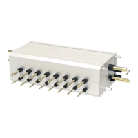
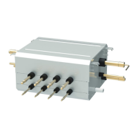
GMV6 HR Mode Exchange Box
24
R410A refrigerant system
Total rated capacity of downstream
indoor units: X(kW)
Model
Y-type branch X≤16 FQ01B/A
Piping size between Mode Exchange Box and downstream indoor unit (“b
、
c
、
d
、
g”)
Total rated capacity of downstream
indoor units: X (kW)
Piping size between mode exchange box and downstream indoor unit
Gas pipe/mm Liquid pipe/mm
2.8<X≤5.0 Φ12.7 Φ6.35
5.0<X≤14 Φ15.9 Φ9.52
14<X≤16 Φ19.05 Φ9.52
Size of connection pipe between indoor branch and indoor unit should be consistent with the
connection pipe of indoor unit.
Piping between indoor branch and indoor unit “e
、
f
、
i
、
j
、
k”
Rated capacity of indoor units
C(kW)
Size of connection pipe between indoor branch and indoor unit
Gas pipe/mm Liquid pipe/mm
C≤2.8 Φ9.52 Φ6.35
2.8<C≤5.0 Φ12.7 Φ6.35
5.0<C≤14 Φ15.9 Φ9.52
14<C≤16 Φ19.05 Φ9.52
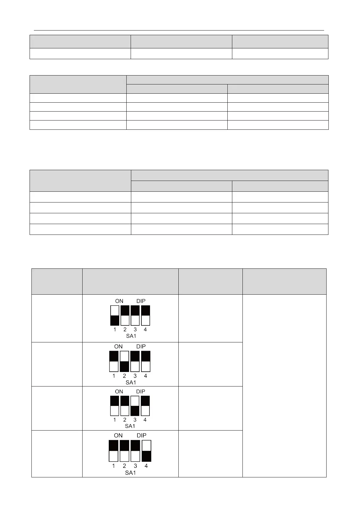
4.2.7.3 Connecting Method for Indoor Unit with Capacity of over 16kW
When connecting to the indoor unit with capacity of over 16 kW, it is not allowed to connect with
only one branch; it must use two branches controlled by the same mainboard for parallel connection.
Parallel
connection
Dial code
communication
connection for mode
Remarks
Indoor unit No.1
and No.2
“1D1 1D2” or “2D1 2D2”
Parallel connection can be
conducted only as the
combination of this table; it is
not allowed to otherwise
connect. Note that after the
connection, manually set the
SA1 dial code of corresponding
mainboard, and dial the code
as shown in the table.
Indoor unit No.2
and No.3
“2D1 2D2” or “3D1 3D2”
Indoor unit No.3
and No.4
“3D1 3D2” or “4D1 4D2”
Indoor unit No.1
and No.2
Indoor unit No.3
and No.4
“1D1 1D2” or “2D1 2D2”
and
“3D1 3D2” or “4D1 4D2”