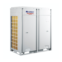
Ultra Heat GMV Multi VRF_Heat Recovery Serial
48
Refrigerant is normal. Next step will
start automatically.
12_Confirm
debugging
startup
Ready for units to start debugging.
The unit starts up in the status of
manual calculation of refrigerant
charging amount.
Debugging for cooling mode.
(Debugging operation mode, the
system will select automatically
with no need of manual setting).
Malfunction occurs when
debugging for cooling mode.
Debugging for heating mode.
(Debugging operation mode, the
system will select automatically
with no need of manual setting).
Malfunction occurs when
debugging for heating mode.
Display of related error code:
Master unit hasn’t been set. LED1 will display CC.
XXXX means the project code of IDU with error. 3s
later, d3 will be displayed. For instance, if no.100 IDU
has d3 error, then the LED1 will display circularly as
below: 01(2s later), 00(2s later), d3.
5.2.2.2 Debugging operation mode
Ultra Heat GMV multi VRF system has two debugging modes: one is direct operation on main board
of outdoor units while the other is PC operation via special software. In PC software debugging,
indoor/outdoor parameters can be displayed and historical data can be recorded and inquired.
(Operation details can be found in relevant instruction manuals)
(1) Debugging through operation on main board of outdoor units
In this debugging mode, following debugging functions are included on the main board:
Step 1: Front panel of the outdoor units must be fully closed. Open the debugging window of each
basic module.
Step 2: Disconnect power for outdoor units. According to design requirements of external static
pressure, set up corresponding static pressure mode for the units. Setting methods can be seen in
Outdoor Fan Static Pressure Setup S2 of Technical service manual; Low noise setting method can also
be seen in low noise setting S1 of Technical service manual.
Step 3: Disconnect power for outdoor units and set one module as a master unit. Setting methods

 Loading...


