Ultra Heat GMV Multi VRF_Heat Recovery Serial
41
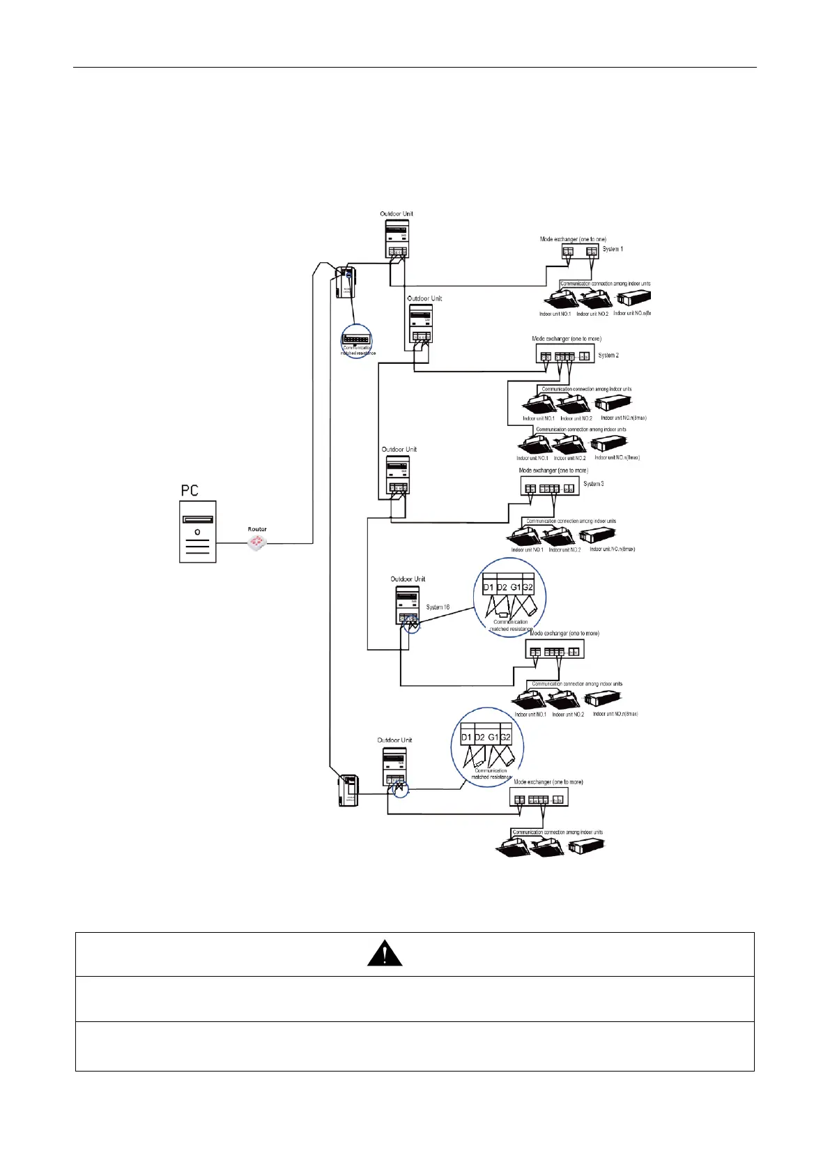
4.8.3 Communication connection of central controlling units
NOTICE! The centralized controller can be installed when it is necessary.
Port connection G1 and G2 on the wiring board of master unit and slave unit among each multi VRF
system (see below)
Fig.50
4.9 External Electrical Wiring Diagram
(1) Each unit should be equipped with a circuit breaker for short circuit protection and exceptional overload protection.
In general, circuit breaker is at OFF status.
(2) During operation, all indoor units and outdoor units belonging to the same system must be kept energized status.
Otherwise, the unit can’t operate normally.
 Loading...