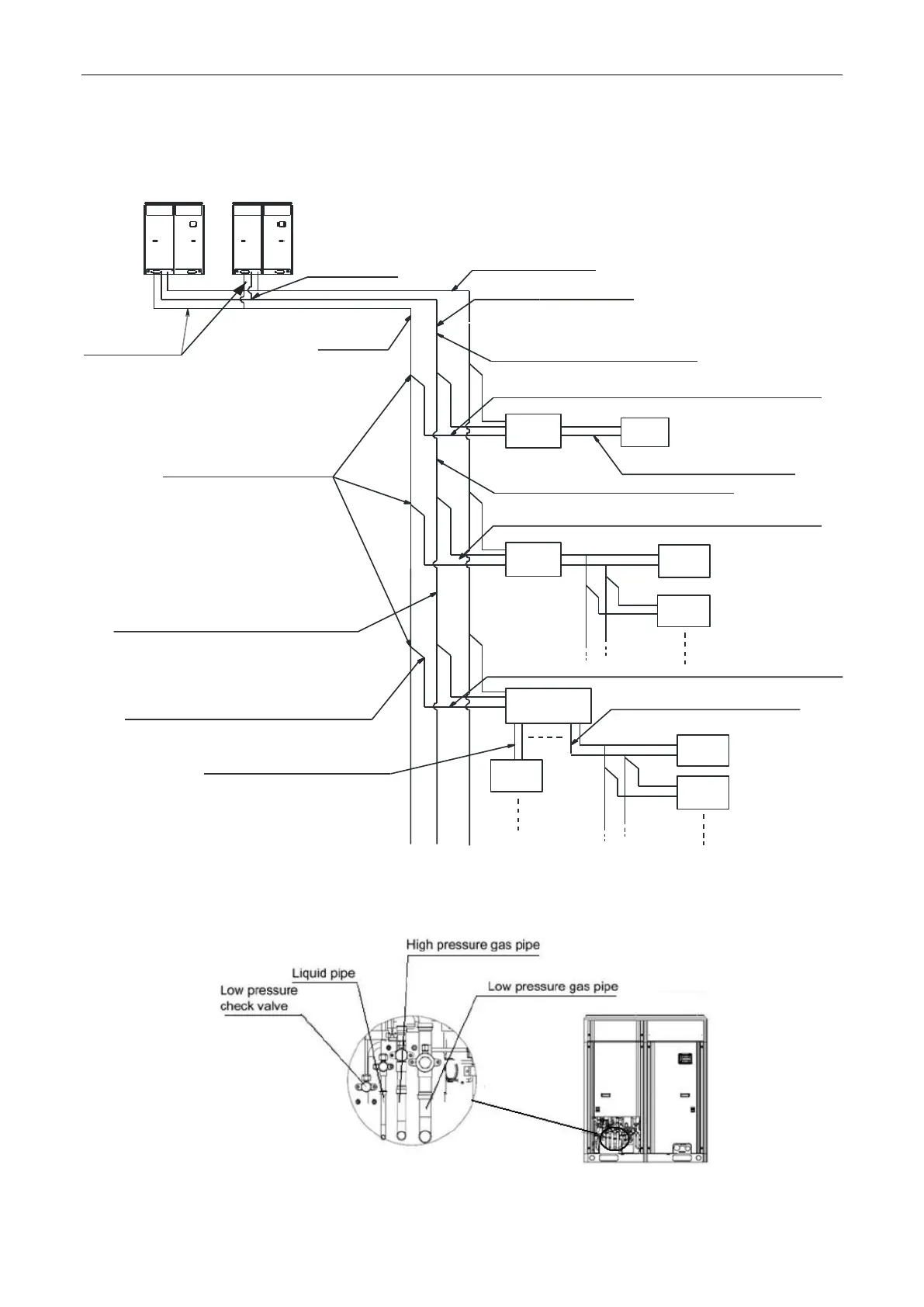
4.3 Connection Pipe
4.3.1 Schematic diagram of piping connection
High pressure gas pipe
Liquid pipe
Outdoor
connection pipe
Lowpressure
gaspipe
Branch between indoor units
Connection pipe between outdoor
branch and the first indoor branch
Connection pipe between indoor branch and indoor units
Mode
exchanger
Mode
exchanger
Mode
exchanger
Indoor
unit 1
Indoor
unit 2
Indoor
unit 3
Indoor
unit 4
Indoor
unit 5
Indoor
unit 6
Connection pipe between mode
exchanger and indoor units
Connection pipe between indoor branchs
Connection pipe between indoor branch and mode exchanger
Connection pipe between mode
exchanger and indoor branch
Connection pipe between indoor branchs
Connection pipe between indoor branchs
Connection pipe between
mode exchanger and indoor units
Connection pipe between indoor branch and indoor units
Module1 Module 2
Branch between
outdoor units
Fig.15
4.3.2 Schematic diagram of piping sequence
 Loading...