EasyManuals Logo

Gree Ultra Heat GMV Multi VRF Series User Manual

Gree Ultra Heat GMV Multi VRF Series
72 pages
To Next Page IconTo Next Page
To Previous Page IconTo Previous Page
Page #25 background imageLoading...
Page #25 background image
Ultra Heat GMV Multi VRF_Heat Recovery Serial
20
Fig.22
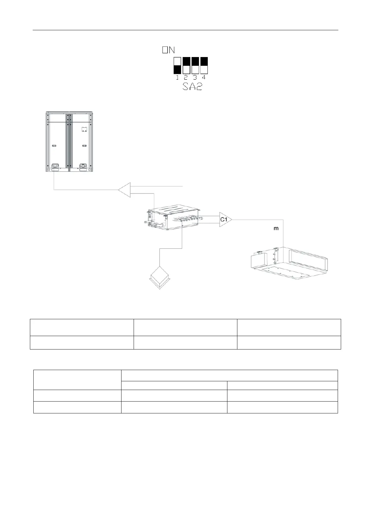
Connecting method is shown as in the Fig.23.
Fig.23
4.3.6.1 Branch selection of indoor unit of mode exchanger (C1)
R410A refrigerant system
Total rated capacity of downstream
indoor units: X(Btu/h)
Model
Y-type branch
48500<X≤96000
FQ01B/A
4.3.6.2 Pipe size between mode exchanger and downstream and indoor unit (“m”)
Rated capacity of indoor units:
X ((Btu/h)
Size of connection pipe between indoor branch and indoor unit
Gas pipe mm(inch)
Liquid pipe mm(inch)
48500X≤72000
Φ19.05(3/4)
Φ9.52(3/8)
72000X≤96000
Φ22.2(7/8)
Φ9.52(3/8)
4.4 Installation of the Connection Pipe
Notice: before welding the pipeline sealing cap, please make sure theres no refrigerant in pipeline.
If welding it directly, it may cause unnecessary property damage or personal injury.
4.4.1 Precautions when installing the connection pipe

Questions and Answers:

Question and Answer IconNeed help?

Do you have a question about the Gree Ultra Heat GMV Multi VRF Series and is the answer not in the manual?

Gree Ultra Heat GMV Multi VRF Series Specifications

General IconGeneral
BrandGree
ModelUltra Heat GMV Multi VRF Series
CategoryAir Conditioner
LanguageEnglish

Related product manuals