Do you have a question about the Gree VIR18HP230V1B and is the answer not in the manual?
Details the technical specifications for cooling, heating, power, and physical dimensions.
Illustrates the physical dimensions and layout of the indoor and outdoor units.
Provides essential safety precautions and guidelines for installation and maintenance.
Outlines the step-by-step process for installing the indoor and outdoor units.
Details crucial safety measures and procedures before performing maintenance.
Lists error codes displayed by the unit and their corresponding causes and troubleshooting.
Provides guidance for diagnosing and resolving major malfunctions in the unit.
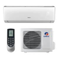
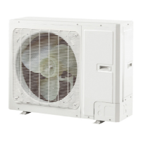
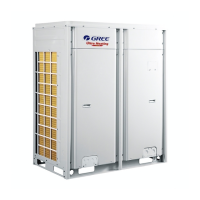
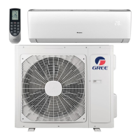
Provides a concise overview of the air conditioning unit models and components.
Details the technical specifications for cooling, heating, power, and physical dimensions.
Details the technical specifications for cooling, heating, power, and physical dimensions.
Illustrates performance curves related to compressor speed and current draw.
Covers the electrical connections, including wiring and PCB diagrams.
Illustrates the electrical connections and wiring layout for the unit.
Displays noise levels for indoor and outdoor units based on fan speed and frequency.
Provides detailed cooling and heating performance data under rated conditions.
Illustrates the physical dimensions and layout of the indoor and outdoor units.
Shows the dimensions and mounting details for the indoor unit.
Depicts the flow of refrigerant through the indoor and outdoor units.
Shows the layout and component identification on the printed circuit board.
Introduces the buttons and display icons of the remote controller.
Explains the function of each button on the remote controller.
Describes the meaning of various icons shown on the remote controller's display screen.
Describes how to activate and use the energy-saving mode.
Details the procedure to activate the 8°C heating function for low-temperature protection.
Explains the operation of Cooling, Drying, Heating, AUTO, and Fan modes.
Covers additional control functions like Buzzer, Auto button, Auto fan, Sleep, Timer, Memory, and Health functions.
Explains the conditions and procedures for starting and finishing the defrosting operation.
Details the control logic for compressor, outer fans, and 4-way valve operations.
Explains protection measures against freezing conditions, including frequency limits and power turn-off.
Describes overload protection logic for cooling and dehumidifying modes, including frequency limits and power turn-off.
Details protection against voltage sags in the DC link.
Explains protection measures for communication failures between units.
Covers module protection and overheating protection for the unit.
Emphasizes critical safety warnings and precautions for installation and maintenance work.
Lists essential safety measures related to electrical connections and power handling.
Lists the parts to be checked before proceeding with the installation.
Provides guidelines for selecting the optimal installation location for both indoor and outdoor units.
Illustrates the required clearances and dimensions for installing the indoor and outdoor units.
Outlines the overall workflow for installing the air conditioning unit.
Details the necessary electrical connections, including safety and grounding requirements.
Step-by-step instructions for installing the wall-mounting frame for the indoor unit.
Details the process of connecting the refrigerant pipes to the indoor unit.
Details the process of securely mounting the support structure for the outdoor unit.
Describes how to connect the refrigerant pipes between the indoor and outdoor units.
Instructions for making the electrical connections to the outdoor unit.
Step-by-step procedure for using a vacuum pump to evacuate the system.
Methods for detecting refrigerant leaks using a detector or soap water.
Procedures for conducting a test run to ensure the unit operates correctly.
Focuses on troubleshooting common issues within the indoor unit.
Provides a flowchart for diagnosing and resolving temperature sensor issues.
Lists error codes specific to the outdoor unit and their causes.
Provides a flowchart for diagnosing and resolving issues with the indoor unit fan motor.
Offers a troubleshooting guide for communication failures between indoor and outdoor units.
Guides on diagnosing and resolving capacity charging issues related to the outdoor control board (AP1).
Addresses IPM protection, desynchronization, and compressor overcurrent malfunctions.
Outlines the diagnostic process for anti-high temperature and overload protection faults.
Provides a troubleshooting guide for situations where the unit fails to start up correctly.
Details the diagnostic steps for issues related to compressor synchronism and voltage.
Guides on diagnosing overload and discharge malfunctions, including expansion valve and refrigerant checks.
Provides a troubleshooting guide for communication failures within the outdoor unit.
Details the diagnostic process for issues within the outdoor unit's communication circuit.
Addresses problems encountered when the air conditioner fails to start up.
Troubleshoots common problems related to poor cooling or heating performance.
Guides on troubleshooting the outdoor unit fan motor when it cannot operate.
Addresses troubleshooting for situations where the compressor cannot operate.
Displays the exploded view of the indoor unit, showing the arrangement of its components.
Lists all parts of the indoor unit with their corresponding part codes and quantities.
Step-by-step instructions for disassembling the indoor unit components.
Instructions for removing the air filters from the indoor unit.
Details the process of removing the horizontal air louvers.
Instructions for removing the handle, valve cover, and top cover of the outdoor unit.
Steps for removing the grille and outer casing of the outdoor unit.
Details the process of removing the 4-way valve assembly, including desoldering.
Instructions for removing the compressor from the outdoor unit.
Steps for removing the condenser assembly from the outdoor unit.
Instructions for removing the gas and liquid valves from the 24K outdoor unit.
Instructions for removing the compressor from the 24K outdoor unit.
Provides a reference table for converting between Celsius and Fahrenheit temperatures.
Details specifications and requirements for connecting pipes, including length and refrigerant charge.
Explains the correct procedure for expanding pipes to prevent refrigerant leakage.
Lists resistance values for temperature sensors at various temperatures for diagnostic purposes.
Provides resistance values for ambient temperature sensors at different temperatures.
Explains the correct procedure for expanding pipes to prevent refrigerant leakage.
| Brand | Gree |
|---|---|
| Model | VIR18HP230V1B |
| Category | Air Conditioner |
| Language | English |