Universal Single Width Fans 7
®
R
o
t
a
t
i
o
n
R
o
t
a
t
i
o
n
R
o
t
a
t
i
o
n
R
o
t
a
t
i
o
n
POOR
POOR
GOOD
POORGOOD
Three fan wheel diameters
GOOD
Three fan wheel diameters
3/4 to one
fan
inlet
diameter
3/4 to
one fan
wheel
diameter
One fan
diameter
3/4 to
one fan
wheel
diameter
SYSTEM EFFECT FACTORS CURVES
STATIC PRESSURE LOSS
1.2
1.0
0.8
0.6
0.4
0.2
0.0
0 5 10 15 20 25 30 35 40 45
FPM X 100
OUTLET VELOCITY
CURVE 1
CURVE 2
CURVE 3
CURVE 4
3/4 to one
fan
inlet
diameter
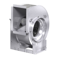
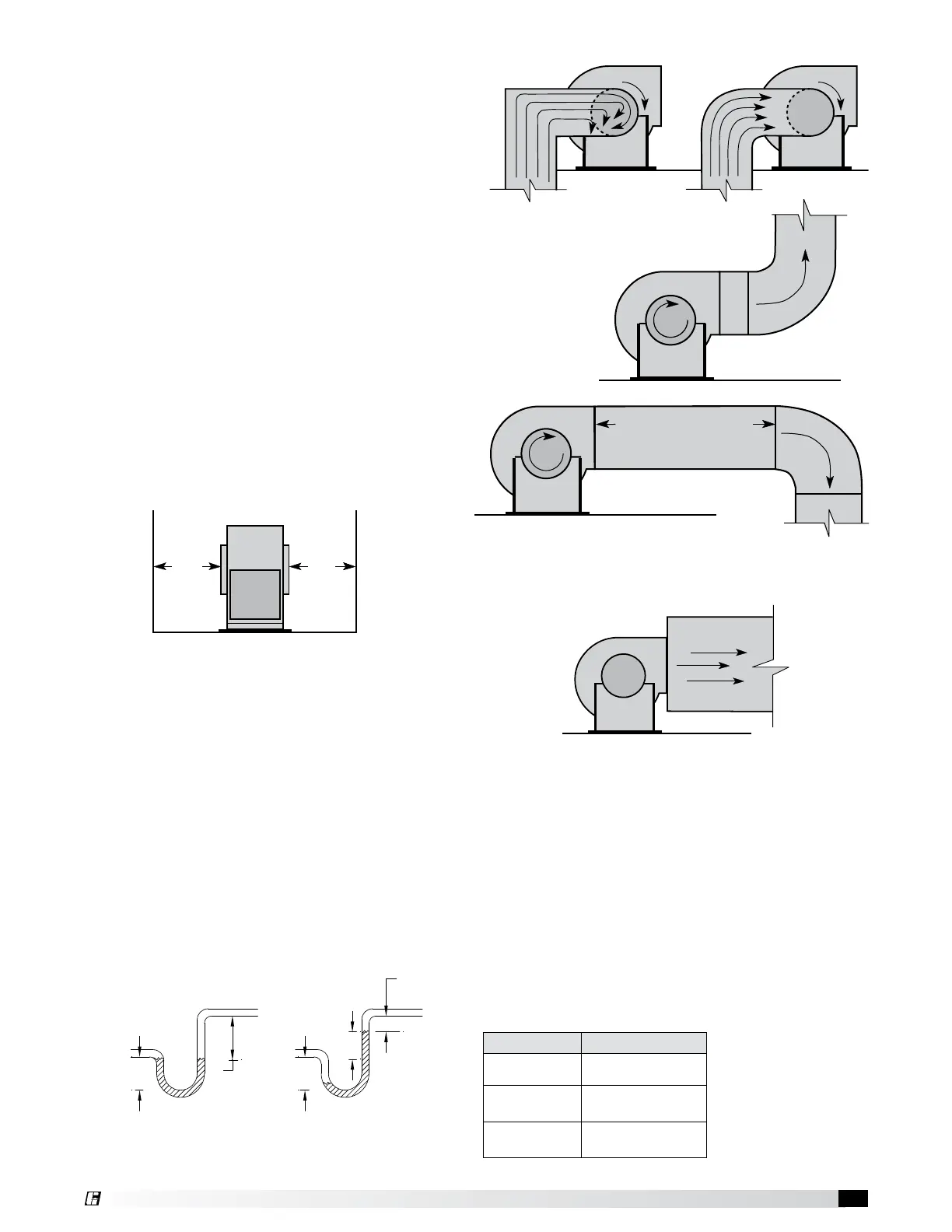
Non-Ducted Installations
Inlet Clearance - Installation of a fan with an
open inlet too close to a wall or bulkhead will cause
reduced fan performance. It is desirable to have
a minimum of three-fourths of a wheel diameter
between the fan inlet and the wall.
Free Discharge - Free or abrupt discharge into a plenum results
in a reduction in fan performance. The effect of discharge static
regain is not realized.
R
o
t
a
t
i
o
n
R
o
t
a
t
i
o
n
R
o
t
a
t
i
o
n
R
o
t
a
t
i
o
n
Turning
Vanes
Turning
Vanes
POOR
POOR
GOOD
POORGOOD
Length of Straight Duct
GOOD
1 Fan
Wheel
Diameter
3/4 to one
fan
wheel
diameter
3/4 to one
fan
wheel
diameter
3/4 to one
fan
wheel
diameter
3/4 to one
fan
wheel
diameter
One fan
diameter
3/4 to one
fan
wheel
diameter
SYSTEM EFFECT FACTORS CURVES
STATIC PRESSURE LOSS
1.2
1.0
0.8
0.6
0.4
0.2
0.0
0 5 10 15 20 25 30 35 40 45
FPM X 100
OUTLET VELOCITY
CURVE 1
CURVE 2
CURVE 3
CURVE 4
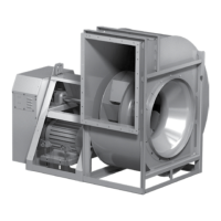
Single Fan Installation
R
o
t
a
t
i
o
n
R
o
t
a
t
i
o
n
POOR
GOOD
POORGOOD
Three fan wheel diameters
GOOD
Three fan wheel diameters
3/4 to one
fan
inlet
diameter
3/4 to
one fan
wheel
diameter
One fan
diameter
3/4 to
one fan
wheel
diameter
SYSTEM EFFECT FACTORS CURVES
STATIC PRESSURE LOSS
1.2
1.0
0.8
0.6
0.4
0.2
0.0
0 5 10 15 20 25 30 35 40 45
FPM X 100
OUTLET VELOCITY
CURVE 1
CURVE 2
CURVE 3
CURVE 4
3/4 to one
fan
inlet
diameter
Check local codes for proper disposal of drain water
which has been in contact with the exhaust air.
Fans used for grease exhaust need to be equipped
with a separate grease collector.
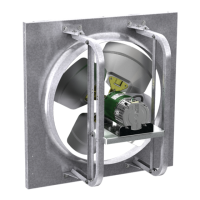
Inlet Spin - Inlet spin is a frequent cause of reduced fan
performance. The change in fan performance is a function
of the intensity of spin and not easily defined. The best
solution is proper duct design and airflow patterns.
Turning vanes reduce the effects of inlet spin.
Series Drain Options
100 Drain only *
300
No drain
Drain with plug
500
No drain
Drain with plug
* 1 inch (25.4 mm) non-threaded drain hole
Fan Drainage Piping and Trap Detail (by others)
Fans may have been supplied with an optional drain. Drains are located at the underside of the scroll housing.
The drain may need to be connected to a drainage system to ensure proper disposal of any water or condensate
that may occur.
• Drain connections with a plug are 1 inch (25.4mm) MNPT.
• Installed piping to have a downward angle to allow for drainage.
• Fill traps to recommended level before start-up.
Note: A conservative method of trap design is to set N = total static pressure.
Positive Pressure Trap
RECOMMENDED DRAIN TRAP DESIGN
(TRAP BY OTHERS)
FAN BYPASS
AIR PLENUM
ENERGY RECOVERY
PLENUM
SUBFLOOR
SUBFLOOR
1.25 NPT
.75 NPT
*BASED ON STANDARD
VEKTOR ERS CURB HEIGHTS
*
*
ROOF
CURB
ROOF
CURB
P.O.BOX 410 SCHOFIELD, WISCONSIN 54476-0410
TITLE
DRAWN BY
ECO
B
ENG. REF.
DATE
SUPERSEDES
SCALE
CAD DRAWING NO.
FAUST
06/29/2009
1/8
VK-ERS
N = Negative fan pressure (inches W.C.)
H = N - 0.5 inches minimum
Note: A conservation method of trap design is to set
N = TSP and P = TSP (TSP = Total Static Pressure)
H/2
H/2
H
1.25 inch minimum
N
FAN ON
FAN OFF
NEGATIVE PRESSURE TRAP
14.750
14.000
NOTE: INSULATION OR OTHER MEANS
OF FREEZE PROTECTION MAY BE
REQUIRED IN CERTAIN CLIMATES
RECOMMENDED DRAIN TRAP DESIGN
(TRAP BY OTHERS)
N = Negative fan pressure (inches W.C.)
H = N - 0.5 inches minimum
NOTE: A conservative method of trap design is to set
N = Total Static Pressure and P = Total Static Pressure
H/2 H/2
H
1.25 inch
minimum
N
FAN ONFAN OFF
Connect
this end
to fan drain.
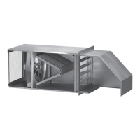
Ducted Outlet Installations
Discharge Duct Turns - Duct turns located near the fan discharge should
always be in the direction of the fan rotation.
Fan performance is reduced when duct turns are made immediately off the
fan discharge. To achieve cataloged fan performance there should be at
least three equivalent duct diameters of straight ductwork between the fan
discharge and any duct turns.
R
o
t
a
t
i
o
n
R
o
t
a
t
i
o
n
R
o
t
a
t
i
o
n
R
o
t
a
t
i
o
n
POOR
POOR
GOOD
POORGOOD
Three fan wheel diameters
GOOD
Three fan wheel diameters
3/4 to one
fan
inlet
diameter
3/4 to
one fan
wheel
diameter
One fan
diameter
3/4 to
one fan
wheel
diameter
SYSTEM EFFECT FACTORS CURVES
STATIC PRESSURE LOSS
1.2
1.0
0.8
0.6
0.4
0.2
0.0
0 5 10 15 20 25 30 35 40 45
FPM X 100
OUTLET VELOCITY
CURVE 1
CURVE 2
CURVE 3
CURVE 4
3/4 to one
fan
inlet
diameter
 Loading...