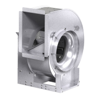
Universal Single Width Fans6
Ducted Inlet Installations
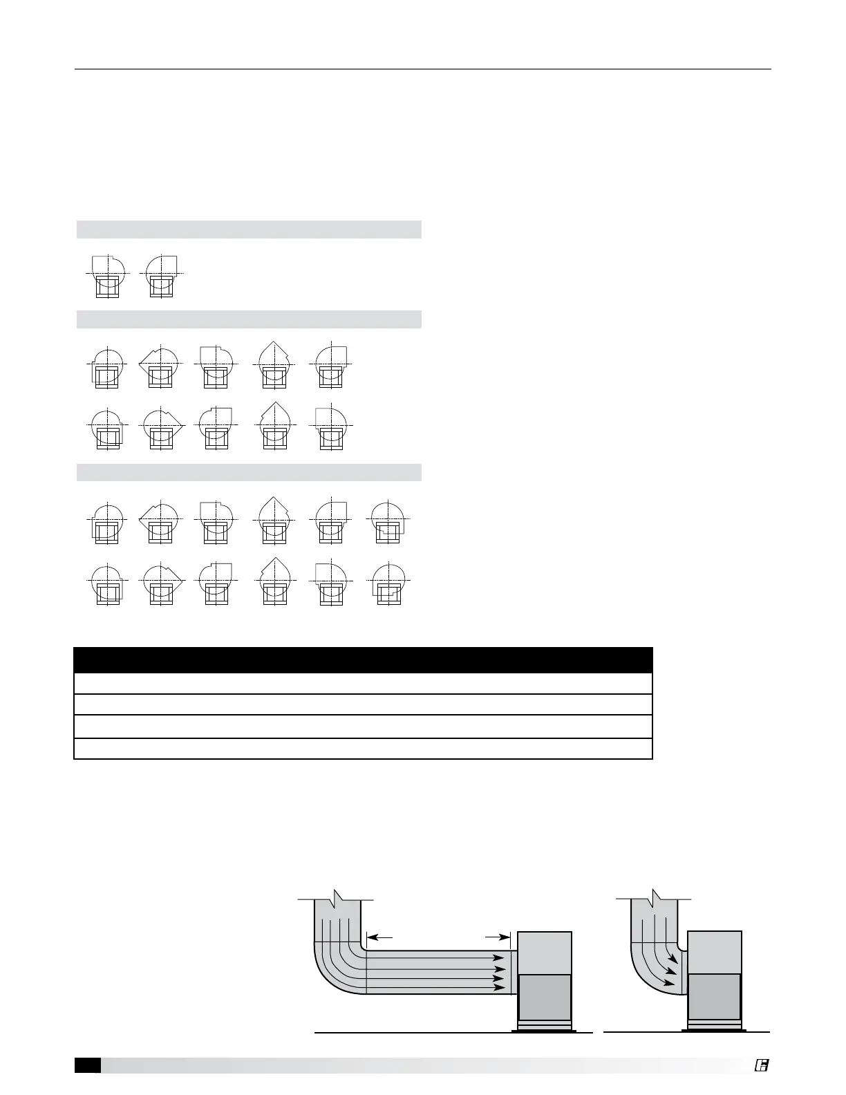
Inlet Duct Turns - Installation
of a duct turn or elbow too
close to the fan inlet reduces
fan performance because air
is loaded unevenly into the
fan wheel. To achieve full fan
performance, there should be at
least three fan wheel diameters
between the turn or elbow and
the fan inlet.
Move the fan to the desired location. Check and tighten fasteners throughout the unit and then fasten securely
through mounting holes provided in the base angles. The unit must be set level (shimming may be necessary).
Flexible duct connections and vibration isolators should be used where noise is a factor.
The motor voltage and ampere rating must be checked for compatibility with the electrical supply prior to
final electrical connection. Supply wiring to the fan must be properly fused, and conform to local and national
electrical codes.
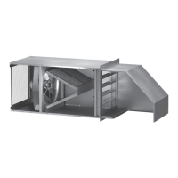
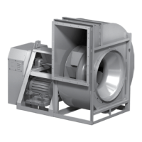
Series 300
Series 500
CW BH
CCW BH
CW BAU
CCW BAU
CW UB
CCW UB
CCW TH
CW TH
CW DB
CCW DB
CW TAU
CCW TAU
CW BH
CCW BH
CW BAU
CCW BAU
CW UB
CCW UB
CCW TH
CW TH
CW TAU
CCW TAU
XUEF-300 and XUEF-400
CW BH
CCW BH
CW BAU
CCW BAU
CW UB
CCW UB
CCW TH
CW TH
CW TAU
CCW TAU
VUSF-300 and VUSF-400
VCSW
CW BH
CCW BH
CW BAU
CCW BAU
CW UB
CCW UB
CCW TH
CW TH
CW DB
CCW DB
CW TAU
CCW TAU
CW BH
CCW BH
CW BAU
CCW BAU
CW UB
CCW UB
CCW TH
CW TH
CW TAU
CCW TAU
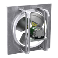
Series 100
CW UB CW TH
VUSFD-100 and VUSF-100
CW UB CW TH
XUEFD-100 and XUEF-100
CW UB CW TH
Discharge Positions
R
o
t
a
t
i
o
n
R
o
t
a
t
i
o
n
R
o
t
a
t
i
o
n
R
o
t
a
t
i
o
n
POOR
POOR
GOOD
POOR
GOOD
Three fan wheel diameters
GOOD
Three fan wheel diameters
3/4 to one
fan
inlet
diameter
3/4 to
one fan
wheel
diameter
One fan
diameter
3/4 to
one fan
wheel
diameter
SYSTEM EFFECT FACTORS CURVES
STATIC PRESSURE LOSS
1.2
1.0
0.8
0.6
0.4
0.2
0.0
0 5 10 15 20 25 30 35 40 45
FPM X 100
OUTLET VELOCITY
CURVE 1
CURVE 2
CURVE 3
CURVE 4
3/4 to one
fan
inlet
diameter
Installation
The discharge is factory set as specified by customer
order, however, certain sizes can be rotated to other
discharge positions in the field, if necessary. If rotating
the fan housing, accommodations may need to be
made for the fan to drain properly.
USF Series 100 - Rotatable housings are standard.
Removal of the housing bolts, inlet cone and wheel
allows the discharge to be rotated to the clockwise
positions shown to the left. For models with EC
motors, the motor nuts on the inside of the scroll
will also need to be removed. Fan rotation is always
specified from the drive side of the housing.
USF Series 300 - Rotatable housings are standard
on sizes 49 and less. Removal of the housing bolts,
inlet cone and wheel allows the discharge to be
rotated to the positions shown to the left. Fan rotation
is always specified from the drive side of the housing.
USF Series 500 - Rotatable housings are standard
on sizes 30 and less, arrangements 1, 9 and 10, and
Class 0, I and II. Sizes 33-73, as well as fan classes III
and IV are not field rotatable. Removal of the housing
bolts, inlet cone and wheel allows the discharge to
be rotated to the positions shown to the left. For
downblast (DB) discharge position, a portion of the
frame angle must be removed. Fan rotation is always
specified from the drive side of the housing.
R
o
t
a
t
i
o
n
R
o
t
a
t
i
o
n
R
o
t
a
t
i
o
n
R
o
t
a
t
i
o
n
POOR
POOR
GOOD
POOR
GOOD
Three fan wheel diameters
GOOD
Three fan wheel diameters
3/4 to one
fan
inlet
diameter
3/4 to
one fan
wheel
diameter
One fan
diameter
3/4 to
one fan
wheel
diameter
SYSTEM EFFECT FACTORS CURVES
STATIC PRESSURE LOSS
1.2
1.0
0.8
0.6
0.4
0.2
0.0
0 5 10 15 20 25 30 35 40 45
FPM X 100
OUTLET VELOCITY
CURVE 1
CURVE 2
CURVE 3
CURVE 4
3/4 to one
fan
inlet
diameter
NOTE
Existing holes will need to be plugged with self-threading fasteners.
Some field housing rotations will require drilling into the fan housing.
All grease fan applications will require the relocation of access door and drain connection.
Trim balance is recommended on the USF series 500.
Installations with inlet or discharge configurations that deviate from this manual may result in reduced fan
performance. Restricted or unstable flow at the fan inlet can cause pre-rotation of incoming air or uneven loading
of the fan wheel yielding large system losses and increased sound levels. Free discharge or turbulent flow in the
discharge ductwork will also result in system effect losses. Refer to the following diagrams for the most efficient
installation conditions.
 Loading...