®
Rooftop Supply Mixed Flow Fans 1
Document 486132
Model KSQ Direct Drive
Rooftop Supply Mixed Flow Fans
Installation, Operation and Maintenance Manual
Please read and save these instructions for future reference. Read carefully before attempting to assemble, install,
operate or maintain the product described. Protect yourself and others by observing all safety information. Failure
to comply with these instructions will result in voiding of the product warranty and may result in personal injury
and/or property damage.
General Safety Information
Only qualified personnel should install this fan.
Personnel should have a clear understanding of these
instructions and should be aware of general safety
precautions. Improper installation can result in electric
shock, possible injury due to coming in contact with
moving parts, as well as other potential hazards. If more
information is needed, contact a licensed professional
engineer before moving forward.
1. Follow all local electrical and safety codes, as well as
the National Electrical Code (NEC) and the National
Fire Protection Agency (NFPA), where applicable.
Follow the Canadian Electric Code (CEC) in Canada.
2. The rotation of the wheel is critical. It must be free
to rotate without striking or rubbing any stationary
objects.
3. Motor must be securely and adequately grounded.
4. Do not spin fan wheel faster than max cataloged fan
RPM. This could cause catastrophic wheel failure.
Adjustments to fan speed significantly affects motor
load. If the fan RPM is changed, the motor current
should be checked to make sure it is not exceeding
the motor nameplate amps.
5. Do not allow the power cable to kink or come in
contact with oil, grease, hot surfaces or chemicals.
Replace cord immediately if damaged.
6. Verify that the power source is compatible with the
equipment.
7. Never open access doors to a duct or fan while the
fan is running.
8. Never remove covers protecting electrical
components while fan is energized.
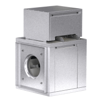
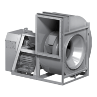
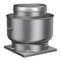
Rooftop Supply Mixed Flow Fans
Fans are direct-driven with mixed flow wheels and feature rigid
construction, high efficiency, and low sound levels. These fans
are designed for filtered roof supply applications such as providing
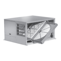
non-tempered make-up air. The fans are available in twelve sizes
and feature permanent, washable aluminum filters.
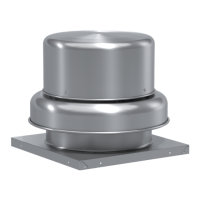
Units that ship fully assembled: Horizontal intake sizes 7 through 24,
bottom intake sizes 7 through 22
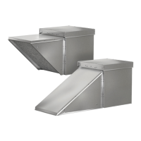
Units that ship with hood knockdown for field assembly: Horizontal intake
sizes 27 through 33, bottom intake sizes 24 through 33
DANGER
Always disconnect, lock, and tag power source before
installing or servicing. Failure to disconnect power
source can result in fire, shock, or serious injury.
CAUTION
When servicing the fan, motor may be hot enough
to cause pain or injury. Allow motor to cool before
servicing.
DANGER
Pour écarter les risques d’incendie, de choc électrique
ou de blessure grave, veiller à toujours débrancher,
verrouiller et étiqueter la source de courant avant
l’installation ou l’entretien.
ATTENTION
Lors de toute intervention sur la soufflante, le moteur
peut être suffisamment chaud pour provoquer une
douleur voire une blessure. Laisser le moteur refroidir
avant toute maintenance.