Ceiling Exhaust and Inline Fans 7
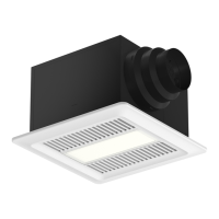
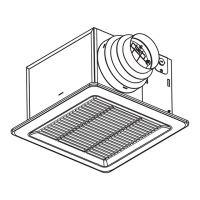
Attach the Grille
1. If lighted grille is being used, plug wire from lighted
grille into accessory socket.
If lighted grille and ceiling radiation damper are being
used, plug wire from lighted grille into ceiling radiation
damper socket. Do not plug wire directly into the fan
socket. Make sure the wire does not interfere with the
ceiling radiation damper operation.
2. Attach grille with two screws provided. Make sure not
to over tighten; over tightening will damage grille.
3. Slide attachment screw covers over the attachment
screws, shown in Figure 8 and 9.
4. If lighted grille is being used, install light bulb(s)
into light socket(s). For fluorescent lights, use 27W
GU24 bulbs. For LED lights, use 10W GU24 bulbs.
Manufacturer has replacement 27W GU24 bulbs, call
1-800-355-5354 to order.
5. If lighted grille is being used, snap lens into place, by
pushing on the outside edges of lens, shown in Fig.9.
To remove lens, use a small screw driver and pry on
one side of lens.
6. Turn on power and check fan and light operation.
A50-90-VG and A90-130-VG Fan Models
These fan models utilize an internal switch to set the fan
to run at one of three flows. Please set three position
switch to desired airflow when installing unit.
Whole House Ventilation
Two-Speed Operation
A90 and 110, B50, 80 and 110 Models
1. Install fan per standard instructions.
2. Fan will operate at the certified airflow rate
when wall switch or integrated sensor is
activated.
3. Fan will operate at user set low speed when
wall switch or integrated sensor is off.
a. User defined flow rate can be set by
adjusting the dial pre-installed in the fan.
Airflow is dependent on overall static
pressure in the ductwork. Airflow will need
to be verified with a measuring device.
4. When servicing fan, ensure the circuit is shut
off at the breaker.
A5 0-9 0
50 70 9 0
90 110 130
A9 0-13 0
FAN
A50-90
50 70 90
90 110 130
A90-130
Fig. 8 Fig. 9
BLACK WIRE
GREEN WIRE
WHITE WIRE
BLACK WIRE
GREEN WIRE
WHITE WIRE
SOLID STATE
SWITCH
RED WIRE
BLACK WIRE
CUSTOMER SUPPLIED
JUNCTION BOX
CUSTOMER
WALL SWITCH
L1 SWITCHED POWER
L2 CONSTANT POWER
RED WIRE
GREEN WIRE
WHITE WIRE
GROUND (EARTH)
NEUTRAL WIRE
GREEN WIRE
LEVER NUT
FAN
SOLID STATE
FAN SPEED CONTROLLER
FAN
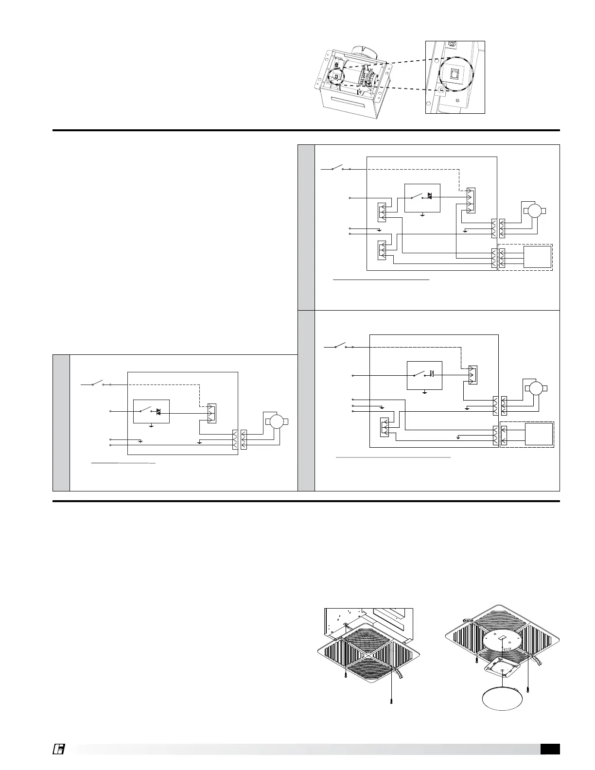
Wiring Diagram - Continuous Ventilation
1. L1 Switched Power: Black Wire - Customer connection for switched power to the fan motor for high speed to be landed in lever nut connector.
2. L2 Constant Power: Red Wire - Provides customer connection for constant power to the fan speed controller.
3. L3 Neutral Power: White Wire - Provides customer connection for neutral power to the fan motor.
4. Green Wire - Provides earth ground for customer connection.
JUNCTION BOX
FAN
CUSTOMER
WALL SWITCH
L1 SWITCHED POWER
BLACK WIRE
CUSTOMER SUPPLIED
RED WIRE
SOLID STATE
FAN SPEED CONTROLLER
SWITCH
SOLID STATE
GREEN WIRE
GREEN WIRE
WHITE WIRE
GROUND (EARTH)
NEUTRAL WIRE
L2 CONSTANT POWER
BLACK WIRE
RED WIRE
WHITE WIRE
BLACK WIRE
RED WIRE
WHITE WIRE
OPTIONAL SENSOR:
MOTION
HUMIDITY, or
MOTION & HUMIDITY
BLACK WIRE
GREEN WIRE
WHITE WIRE
BLACK WIRE
GREEN WIRE
WHITE WIRE
RED WIRE
LEVER NUT
LEVER NUTLEVER NUT
FAN
ACC
RED WIRE
Wiring Diagram - Continuous Ventilation with Sensors
1. L1 Switched Power: Black Wire - Customer connection for switched power to the fan motor for high speed to be landed in lever nut connector.
2. L2 Constant Power: Red Wire - Provides customer connection for constant power to the fan speed controller.
3. L3 Neutral Power: White Wire - Provides customer connection for neutral power to the fan motor.
4. Green Wire - Provides earth ground for customer connection.
Wiring Diagram - Continuous Ventilation with Light & Wall Switch
1. L1 Switched Power: Black Wire - Customer connection for switched power to the fan motor for high speed to be landed in lever nut connector.
2. L2 Constant Power: Red Wire - Provides customer connection for constant power to the fan speed controller.
3. L3 Switched Power: Black Wire - Customer connection for switch power to the light to be connected to the black wire from ACC.
4. Neutral Power: White Wire - Provides customer connection for neutral power to the fan motor.
5. Green Wire - Provides earth ground for customer connection.
WITH SENSORS
WITH LIGHT & WALL SWITCH
JUNCTION BOX
FAN
CUSTOMER
WALL SWITCH
L1 SWITCHED POWER
BLACK WIRE
CUSTOMER SUPPLIED
RED WIRE
SOLID STATE
FAN SPEED CONTROLLER
SWITCH
SOLID STATE
GREEN WIRE
GREEN WIRE
WHITE WIRE
GROUND (EARTH)
NEUTRAL WIRE
L2 CONSTANT POWER
BLACK WIRE
WHITE WIRE
BLACK WIRE
WHITE WIRE
LIGHT
BLACK WIRE
GREEN WIRE
WHITE WIRE
BLACK WIRE
GREEN WIRE
WHITE WIRE
RED WIRE
LEVER NUT
LEVER NUT
FAN
ACC
GREEN WIRE
BLACK WIRE
L3 SWITCHED POWER
BLACK WIRE
GREEN WIRE
WHITE WIRE
BLACK WIRE
GREEN WIRE
WHITE WIRE
SOLID STATE
SWITCH
RED WIRE
BLACK WIRE
CUSTOMER SUPPLIED
JUNCTION BOX
CUSTOMER
WALL SWITCH
L1 SWITCHED POWER
L2 CONSTANT POWER
RED WIRE
GREEN WIRE
WHITE WIRE
GROUND (EARTH)
NEUTRAL WIRE
GREEN WIRE
LEVER NUT
FAN
SOLID STATE
FAN SPEED CONTROLLER
FAN
Wiring Diagram - Continuous Ventilation
1. L1 Switched Power: Black Wire - Customer connection for switched power to the fan motor for high speed to be landed in lever nut connector.
2. L2 Constant Power: Red Wire - Provides customer connection for constant power to the fan speed controller.
3. L3 Neutral Power: White Wire - Provides customer connection for neutral power to the fan motor.
4. Green Wire - Provides earth ground for customer connection.
JUNCTION BOX
FAN
CUSTOMER
WALL SWITCH
L1 SWITCHED POWER
BLACK WIRE
CUSTOMER SUPPLIED
RED WIRE
SOLID STATE
FAN SPEED CONTROLLER
SWITCH
SOLID STATE
GREEN WIRE
GREEN WIRE
WHITE WIRE
GROUND (EARTH)
NEUTRAL WIRE
L2 CONSTANT POWER
BLACK WIRE
RED WIRE
WHITE WIRE
BLACK WIRE
RED WIRE
WHITE WIRE
OPTIONAL SENSOR:
MOTION
HUMIDITY, or
MOTION & HUMIDITY
BLACK WIRE
GREEN WIRE
WHITE WIRE
BLACK WIRE
GREEN WIRE
WHITE WIRE
RED WIRE
LEVER NUT
LEVER NUTLEVER NUT
FAN
ACC
RED WIRE
Wiring Diagram - Continuous Ventilation with Sensors
1. L1 Switched Power: Black Wire - Customer connection for switched power to the fan motor for high speed to be landed in lever nut connector.
2. L2 Constant Power: Red Wire - Provides customer connection for constant power to the fan speed controller.
3. L3 Neutral Power: White Wire - Provides customer connection for neutral power to the fan motor.
4. Green Wire - Provides earth ground for customer connection.
Wiring Diagram - Continuous Ventilation with Light & Wall Switch
1. L1 Switched Power: Black Wire - Customer connection for switched power to the fan motor for high speed to be landed in lever nut connector.
2. L2 Constant Power: Red Wire - Provides customer connection for constant power to the fan speed controller.
3. L3 Switched Power: Black Wire - Customer connection for switch power to the light to be connected to the black wire from ACC.
4. Neutral Power: White Wire - Provides customer connection for neutral power to the fan motor.
5. Green Wire - Provides earth ground for customer connection.
WITH SENSORS
WITH LIGHT & WALL SWITCH
JUNCTION BOX
FAN
CUSTOMER
WALL SWITCH
L1 SWITCHED POWER
BLACK WIRE
CUSTOMER SUPPLIED
RED WIRE
SOLID STATE
FAN SPEED CONTROLLER
SWITCH
SOLID STATE
GREEN WIRE
GREEN WIRE
WHITE WIRE
GROUND (EARTH)
NEUTRAL WIRE
L2 CONSTANT POWER
BLACK WIRE
WHITE WIRE
BLACK WIRE
WHITE WIRE
LIGHT
BLACK WIRE
GREEN WIRE
WHITE WIRE
BLACK WIRE
GREEN WIRE
WHITE WIRE
RED WIRE
LEVER NUT
LEVER NUT
FAN
ACC
GREEN WIRE
BLACK WIRE
L3 SWITCHED POWER
BLACK WIRE
GREEN WIRE
WHITE WIRE
BLACK WIRE
GREEN WIRE
WHITE WIRE
SOLID STATE
SWITCH
RED WIRE
BLACK WIRE
CUSTOMER SUPPLIED
CUSTOMER
WALL SWITCH
L1 SWITCHED POWER
L2 CONSTANT POWER
RED WIRE
GREEN WIRE
WHITE WIRE
GROUND (EARTH)
NEUTRAL WIRE
GREEN WIRE
LEVER NUT
FAN
SOLID STATE
FAN SPEED CONTROLLER
FAN
Wiring Diagram - Continuous Ventilation
1. L1 Switched Power: Black Wire - Customer connection for switched power to the fan motor for high speed to be landed in lever nut connector.
2. L2 Constant Power: Red Wire - Provides customer connection for constant power to the fan speed controller.
3. L3 Neutral Power: White Wire - Provides customer connection for neutral power to the fan motor.
4. Green Wire - Provides earth ground for customer connection.
JUNCTION BOX
FAN
CUSTOMER
WALL SWITCH
L1 SWITCHED POWER
BLACK WIRE
CUSTOMER SUPPLIED
RED WIRE
SOLID STATE
FAN SPEED CONTROLLER
SWITCH
SOLID STATE
GREEN WIRE
GREEN WIRE
WHITE WIRE
GROUND (EARTH)
NEUTRAL WIRE
L2 CONSTANT POWER
BLACK WIRE
RED WIRE
WHITE WIRE
BLACK WIRE
RED WIRE
WHITE WIRE
OPTIONAL SENSOR:
MOTION
HUMIDITY, or
MOTION & HUMIDITY
BLACK WIRE
GREEN WIRE
WHITE WIRE
BLACK WIRE
GREEN WIRE
WHITE WIRE
RED WIRE
LEVER NUT
LEVER NUTLEVER NUT
FAN
ACC
RED WIRE
Wiring Diagram - Continuous Ventilation with Sensors
1. L1 Switched Power: Black Wire - Customer connection for switched power to the fan motor for high speed to be landed in lever nut connector.
2. L2 Constant Power: Red Wire - Provides customer connection for constant power to the fan speed controller.
3. L3 Neutral Power: White Wire - Provides customer connection for neutral power to the fan motor.
4. Green Wire - Provides earth ground for customer connection.
Wiring Diagram - Continuous Ventilation with Light & Wall Switch
1. L1 Switched Power: Black Wire - Customer connection for switched power to the fan motor for high speed to be landed in lever nut connector.
2. L2 Constant Power: Red Wire - Provides customer connection for constant power to the fan speed controller.
3. L3 Switched Power: Black Wire - Customer connection for switch power to the light to be connected to the black wire from ACC.
4. Neutral Power: White Wire - Provides customer connection for neutral power to the fan motor.
5. Green Wire - Provides earth ground for customer connection.
WITH SENSORS
WITH LIGHT & WALL SWITCH
JUNCTION BOX
FAN
CUSTOMER
WALL SWITCH
L1 SWITCHED POWER
BLACK WIRE
CUSTOMER SUPPLIED
RED WIRE
SOLID STATE
FAN SPEED CONTROLLER
SWITCH
SOLID STATE
GREEN WIRE
GREEN WIRE
WHITE WIRE
GROUND (EARTH)
NEUTRAL WIRE
L2 CONSTANT POWER
BLACK WIRE
WHITE WIRE
BLACK WIRE
WHITE WIRE
LIGHT
BLACK WIRE
GREEN WIRE
WHITE WIRE
BLACK WIRE
GREEN WIRE
WHITE WIRE
RED WIRE
LEVER NUT
LEVER NUT
FAN
ACC
GREEN WIRE
BLACK WIRE
L3 SWITCHED POWER
Continuous Ventilation
Continuous Ventilation with SensorsContinuous Ventilation with Light & Wall Switch
 Loading...