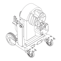
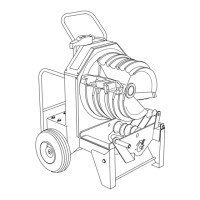
855 Smart Bender
®
Greenlee / A Textron Company 4455 Boeing Dr. • Rockford, IL 61109-2988 USA • 815-397-7070
2
Safety
Safety is essential in the use and maintenance of
Greenlee tools and equipment. This service manual and
any markings on the tool provide information for avoid-
ing hazards and unsafe practices related to the use of
this tool. Observe all of the safety information provided.
Purpose of This Manual
This manual is intended to familiarize authorized
Greenlee service center personnel with the safe
operation and maintenance procedures for the Greenlee
855 Smart Bender, Serial Code ADY.
Keep this manual available to all personnel.
Replacement manuals are available upon request at
no charge at www.greenlee.com.
Other Publications
Instruction Manual: 99943590 (IM 1500)
All specications are nominal and may change as design
improvements occur. Greenlee Textron Inc. shall not be liable for
damages resulting from misapplication or misuse of its products.
Smart Bender is a registered trademark of Greenlee Textron.
Loctite is a registered trademark of Loctite Corporation.
Molex is a registered trademark of Molex Inc.
KEEP THIS MANUAL
Table of Contents
Introduction ................................................................... 2
Important Safety Information .....................................3–4
Grounding Instructions .................................................. 5
Setup ..........................................................................5–6
Adjustments .................................................................. 7
Maintenance .............................................................8–10
Bender Head Disassembly .....................................11–12
Motor Disassembly ...................................................... 13
Trunnion Disassembly ................................................. 13
1/2" to 1-1/4" Side Exploded View ............................. 14
1-1/2" to 2" Side Exploded View ................................. 15
1-1/2" to 2" Roller Support Unit Exploded View ......... 16
Motor and Gearbox Exploded View and Parts List ..... 17
Main Exploded View ...............................................18–19
Main Parts List ........................................................20–21
Electrical Control System Layout and Parts List ......... 22
Power Generation Unit Schematic Diagram,
Parts List, and Layout Diagram ..........................23–25
Input/Output Board Schematic Diagram,
Parts List, and Layout Diagram ..........................26–28
Standard Pendant Switch Schematic Diagram,
Parts List, and Layout Diagram ..........................29–30
Optional Bending Attachments
Exploded View and Parts List .................................. 31
Troubleshooting ......................................................32–38
 Loading...