EasyManua.ls Logo

Greenlee 855 User Manual

Greenlee 855
62 pages
To Next Page IconTo Next Page
Page #1 background imageLoading...
Page #1 background image
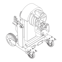
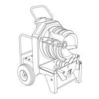
855
SMART BENDER
and 01711 Optional Deluxe Pendant
Serial Code ABL
INSTRUCTION MANUAL
Read and understand all of the instructions and
safety information in this manual before operating
or servicing this tool.
999 2168.5 © 2001 Greenlee Textron IM 1266 REV 15 6/01

Table of Contents

Other manuals for Greenlee 855

Questions and Answers:

Greenlee 855 Specifications

General IconGeneral
BrandGreenlee
Model855
CategorySander
LanguageEnglish

Summary

Description

Safety

Purpose of this Manual

IMPORTANT SAFETY INFORMATION

Safety Alert Symbol

Description of safety alert symbol and signal words.

Grounding Instructions

Specifications

Identification

Transportation

Setup

Operation - Standard Pendant

Operation - Optional Deluxe Pendant

Operation - Installing and Bending Conduit

Variations of Types of Bends

Describes offsets, U-bends, and saddles.

Special Bending Information

Stubs

How to lay out and bend stubs.

Offsets

Controlling the start of the first bend.

Offsets (Controlling the End of the Second Bend)

How to make offsets based on the second bend.

Three-Bend Saddle

How to make a three-bend saddle.

Four-Bend Saddle with Straight

How to make a four-bend saddle.

U-Bends

How to make U-bends.

Special Bending Information Chart

Data table for bending dimensions.

Assembly Instructions for 40 Mil PVC-Coated Rigid Bending Accessories

Adjustments

Squeeze Adjustments

How to adjust conduit squeeze.

Accuracy Adjustments

Adjusting limit switches for bending accuracy.

Maintenance and Adjustments

Retention Cam

Adjusting the retention cam.

Chain Lubrication

Lubricating the drive chain.

Chain Adjustment

Adjusting drive chain tension.

Brake

Adjusting the brake.

Support Rollers

Cleaning and lubricating rollers.

Motor

Motor commutator brush replacement.

Removing and Installing Shoes

How to change bending shoes.

Bender Head Disassembly

Electronics

Disassembly of electronic components.

Rotary Selector Switches

Disassembly of switches.

Pendant Receptacle

Disassembly of receptacle.

Shoes

Removing and installing shoes.

Roller Supports

Disassembly of roller support units.

Retention Cam

Disassembly of retention cam.

Chain

Chain replacement.

Spindle

Spindle disassembly.

Limit Switch Bracket

Limit switch bracket removal.

Squeeze Adjustments

Adjusting squeeze arm.

Brake

Brake disassembly.

Optical Encoder

Optical encoder removal.

Motor Disassembly

Motor removal.

Trunnion Disassembly

Motor and Gearbox Exploded View and Parts List

1/2" to 1-1/4" Side Exploded View

1-1/2" to 2" Side Exploded View

1-1/2" to 2" Roller Support Unit (500 0574.0) Exploded View

Parts List for Shoe and Roller Units

Main Exploded View

Main Parts List

Optional Bending Attachments Parts List

Electrical Control System Layout and Parts List

Power Generation Unit Parts List

Power Generation Unit Schematic Diagram

Power Generation Board Layout Diagram

Input/Output Board Parts List

Input/Output Board Schematic Diagram

Input/Output Board Layout Diagram

Pendant Board Layout Diagram

Pendant Board Schematic Diagram and Parts List

Troubleshooting

Won't Bend - Display Blank

Troubleshooting flow for blank display.

Will Bend - Won't Count

Troubleshooting flow for no count during bend.

Will Bend - Display Blank

Troubleshooting flow for blank display during bend.

Won't Bend - Display On

Troubleshooting flow for display on but no bend.

Bender Runs Backwards

Troubleshooting flow for incorrect bend direction.

Won't Unload - Display On

Troubleshooting flow for unload issues.

Trips Circuit Breaker

Troubleshooting flow for circuit breaker trips.

Won't Stop

Troubleshooting flow for bender not stopping.

Bender Only Runs in One Direction

Troubleshooting flow for unidirectional operation.

Makes Inaccurate Bends

Troubleshooting flow for inaccurate bends.

Related product manuals