Greenlee Textron / Subsidiary of Textron Inc.
32
4455 Boeing Dr., Rockford, IL 61109-2988 815/397-7070
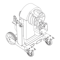
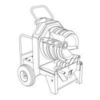
855 Smart Bender™
Bender Head Disassembly
Relay
1. Remove PGU subplate (follow instructions 1-10
above).
2. Remove red and black relay wires (9) (10).
3. Remove two screws, lockwashers and nuts, and
remove relay.
4. Assemble in reverse order.
Transformer
1. Remove four screws securing top round cover and
remove cover.
2. Disconnect transformer from I/O board (21).
3. Remove two screws securing transformer.
4. Assemble in reverse order.
Input/Output Board (I/O)
1. Remove four screws securing top cover and remove
cover.
2. Disconnect receptacle unit (4).
3. Disconnect selector switch (22).
4. Disconnect unload lockout switch (7).
5. Disconnect limit switch (5).
6. Disconnect optical encoder (23).
7. Disconnect brake wire (6).
8. Disconnect PGU-I/O cable (13).
9. Disconnect transformer cable (21).
10. Disconnect I/O-Power Wire Unit (14).
11. Compress the locking tabs on the eight standoffs.
Pull the board just past the locking tabs until all
eight are free, and remove the board completely.
12. Assemble in reverse order, noting proper polarity of
all wires as shown.
ELECTRONICS
Power Generation Board (PGU)
1. Remove four screws securing top round cover and
remove cover.
2. Disconnect ground jump wire, and the white, black,
and green leads of I/O-Power Wire Unit (14).
3. Disconnect power cord neutral (white) wire (3).
4. Disconnect power lead (black) from switch (1).
5. Disconnect PGU-I/O cable (13).
6. Disconnect motor leads (2).
7. Disconnect red, black and two yellow wires to the
rectifier (18) (19) (20).
8. Disconnect the red and black PGU-relay wires
(11) (12).
9. Disconnect relay wire unit (8).
10. Remove four screws securing PGU subplate and
remove subplate.
11. Remove two screws, lockwashers and nuts
securing heat sink to subplate.
12. Compress the locking tabs on the four standoffs.
Pull the PGU board just past the locking tabs until
all four are free, and then remove the board com-
pletely.
13. Assemble in reverse order, noting the proper
polarity of all wires as shown.
Rectifier
1. Remove PGU subplate (follow instructions 1-10
above).
2. Remove screw, lockwasher and nut securing
rectifier.
3. Assemble in reverse order, using heat transfer
grease between rectifier and subplate.
See Electrical Control System Layout for location of key numbers.
Disconnect power supply before
servicing bender. The bender head
should be serviced/disassembled
while on the trunnion base.
Failure to observe this warning can
result in severe injury or death.