Greenlee Textron / Subsidiary of Textron Inc.
55
4455 Boeing Dr., Rockford, IL 61109-2988 815/397-7070
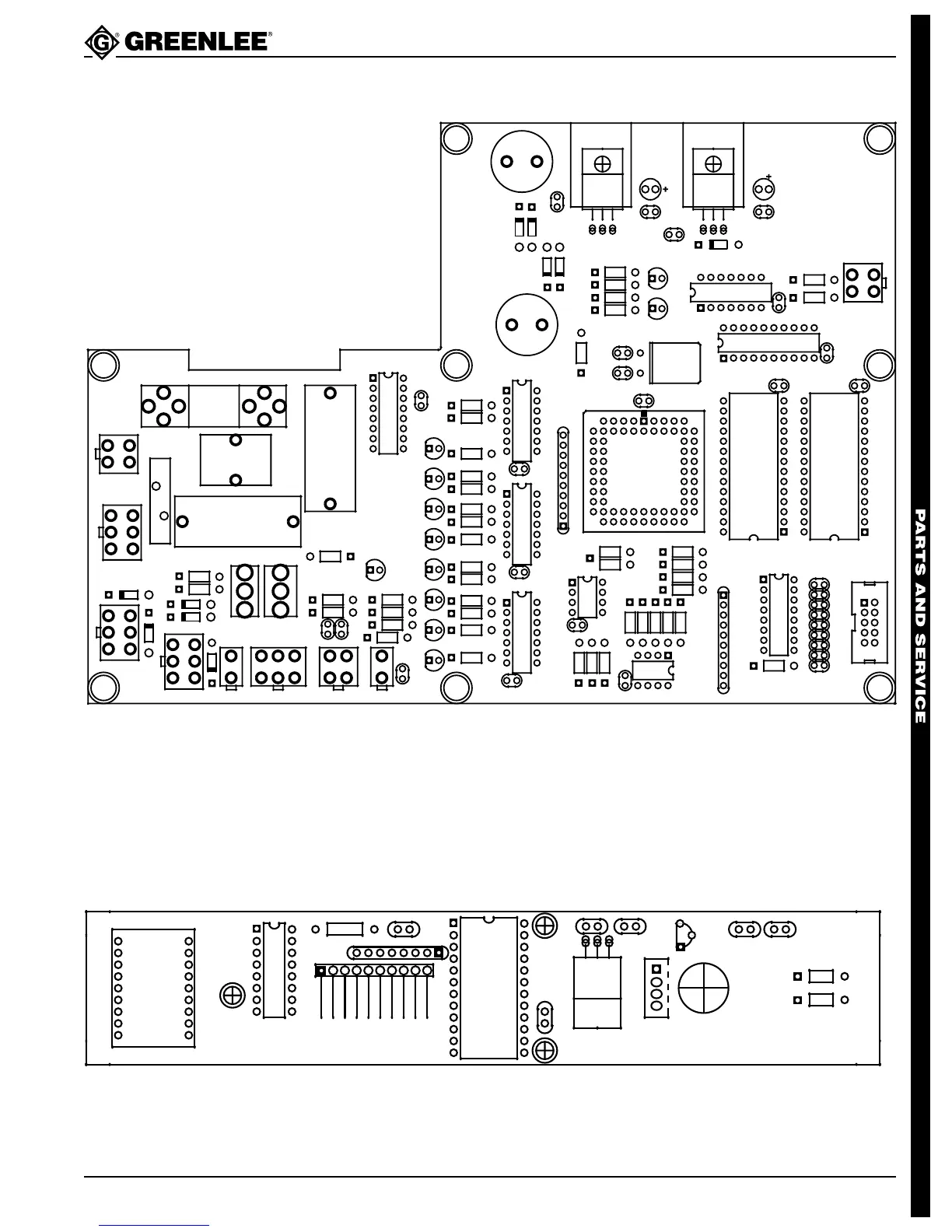
855 Smart Bender™
Input/Output Board Layout Diagram
4321
18
910
5001305.0GREENLEE/TEXTRON INC.
1
1
1
GND
+12V
SDA
SCL
J9
1
2
3
4
REV. 0
J3
J5
STD
DLX
TERMINAL
4
3
21
PENDANT/
TRANSFORMER
5
TO PGU
LOCKOUT
HOMEENCODER
BRAKE
6
4
1
5001706.3
TEXTRON INC.
GREENLEE/
C27
+
C31
TEST1
DIR
PWM
BRAKE
QUAD 1
QUAD 2
HOME 1
HOME 2
J8
J2
J4
+
C28
NEU
LINE
GND
.25A/
250V
1
2
1
3
45 6
2
12
3
4
1
2
1
2
3
4
5
6
C25
L13
VR1
VR2
C33
TEST2
SIGNAL
TEST
1
4
6
5
C26
J7
J6
2
3
3
2
+
J1
1
10
AC POWER
SWITCHES
Pendant Board Layout Diagram