Do you have a question about the Greenlee K425BG and is the answer not in the manual?
Details the K425BG, K4250, K425K58, K425KO tools and their die configurations.
Lists the types of connectors and sleeves the tools can install, covering various wire gauges.
Warns against using the uninsulated tool on live circuits, which could cause severe injury or death.
Highlights that incomplete crimps can cause fires due to improper connector/cable combinations.
Mandates wearing eye protection during operation or servicing to prevent serious eye injury from debris.
Advises on two-handed operation, tool inspection, authorized servicing, and capacity limits to prevent injury.
Guides on selecting and installing the correct dies for specific tool models and connector types.
Details the steps for performing a crimp, including handle operation, over-center mechanism, and multiple crimps.
Explains how to check and readjust the tool's alignment using index marks for proper adjustment.
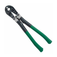
Provides a visual diagram of the mechanical crimping tool with numbered components.
Lists all components of the tool with their respective part numbers and descriptions.
Details available repair kits, specifying which parts are included for different tool models.
| Capacity | Up to 750 MCM |
|---|---|
| Handle Type | Ergonomic |
| Weight | 10 lbs |
| Crimping Force | 12 tons |
| Capacity (Connectors) | Up to 750 MCM |
| Crimp Type | Hexagonal |
| Wire Range | 6 AWG to 750 MCM |
| Die Set Compatibility | Greenlee die sets |
| Material | Steel |
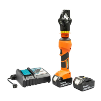
| Voltage | 18V |
| Battery Type | Lithium-ion |
| Type | Battery-powered crimping tool |