11
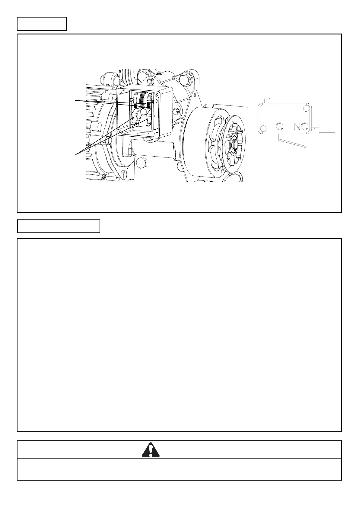
Limit Switch Connecon
The limit switches are connected to the control gear being used via the NORMALLY CLOSED (N/C) and COMMON (COM) of the
microswitch:
Limit seng procedure
ISOLATE MAINS BEFORE SETTING LIMITS
AVOID CRAMMING WIRES INTO LIMIT ENCLOSURE AS IT MAY AFFECT CAM MOVEMENT
Follow the steps below:
1. Manually posion the door in the centre of the opening.
2. Posion one cam to depress a switch and the other so that it is well clear of the switch (note which switch it is that you have
depressed).
For controls with up and down funcons:
Supply power and acvate control in the upward direcon.
If the door travels up, then the limit switch which is engaged by the cam is the CLOSED limit.
If the door doesn't move it is at the OPEN limit.
Connue to Step 3 below
For single buon controls:
Supply power and push the buon.
If the door travels up, then the limit switch which is engaged by the cam is the CLOSED limit.
If the door travels down, then the limit switch which is engaged by the cam is the OPEN limit.
Connue to Step 3 below
3. Isolate power and adjust the limit cams to depress the switches when the shuer reaches its OPEN and CLOSED posions.
4. Supply power and cycles the door between the OPEN and CLOSED posions. Adjust cam posion if necessary.
WARNING
Limits are extremely sensive, a small cam movement may correspond to a large amount of shuer travel.
Limit micro switches
Limit cams
INSTALLATION
SETUP AND ADJUSTMENT
Limit Cam System
Limit Microswitch Terminals