5
PLANNING
Idenfy the type and dimensions of your commercial door. A survey of the applicaon is recommended to see if any of the
requirements below are not applicable with your installaon.
Based on “standard shuer”:
The shuer is correctly spring balanced
The shuer has ≤ 1.0mm x ≥ 100mm slats
The shuer has no wind-locks
A ≥4:1 sprocket rao is used
If any condions above are not met, some consideraon should be given to increasing the sprocket rao, or opener size. The
opener should be installed on the correct side of the commercial door. Consider an In-board mounng kit
(P.No IBMK) if there is insucient side room. Select the side that meets the requirements listed below.
Must have minimum distance of 15mm between mounng plate and door drum sprocket
Must have minimum distance of 200mm between limit housing and imposing structure
Must have minimum clearance of 200mm from the terminal box
Before installing the opener, check that the commercial door is in good mechanical condion, correctly balanced and open
& closes properly.
BOTTOM RAIL WEIGHT AND/OR REVERSE SPRINGING
To provide the shuer with a greater inial closing force, parcularly when fully open, the boom rail should be made heavier.
This can be achieved by aaching approximately 5kg of steel at bar to the upper side of the boom rail. An alternave or
addional method to ensure the shuer will descend when released is to slightly reverse spring the shuer at its fully open
posion. This will give the shuer a bias towards closing when it is in its fully open posion.
NOTE: The shuer must have radial ball or roller bearings on the shuer axle.
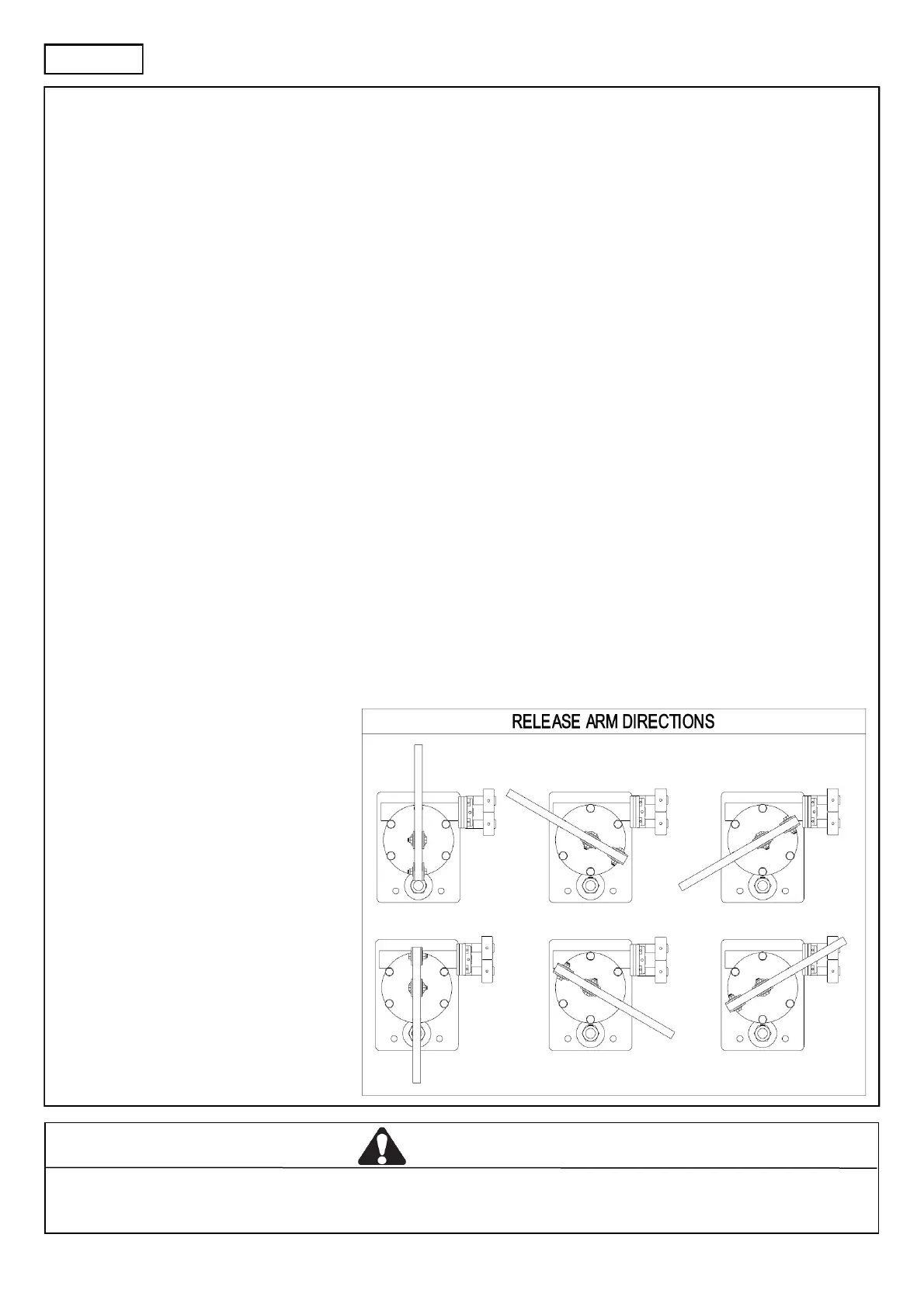
THE RELEASE ARM
The release arm may point in one of the six
direcons allowed by the six bolts on the
plate upon which it is mounted. This is to
allow the fusible linkage to be aached in
the arrangement most convenient to you.
To change the direcon of the arm, remove
the bolt that aaches the boom end of the
arm to the u-bracket. Tilt the arm about the
u-bracket that is connected to the output
sha this will allow access to the boom u-
bracket. The xed u-bracket may be
removed using a spanner on its outside.
Remove the bolt from the plate in the
posion that you wish to t the u-bracket,
screw the u-bracket into this hole. Fit the
spare bolt to the hole where the u-bracket
was. Ret the arm into the u-bracket using
the nut, bolt and washers that were
previously removed.
CAUTION
The roller shuer guides must be ed with mechanical stops that prevent the boom rail from passing through in the opening
direcon. The opener should stall if driving into the mechanical stops.
 Loading...