8
Mounng the Unit (connued)
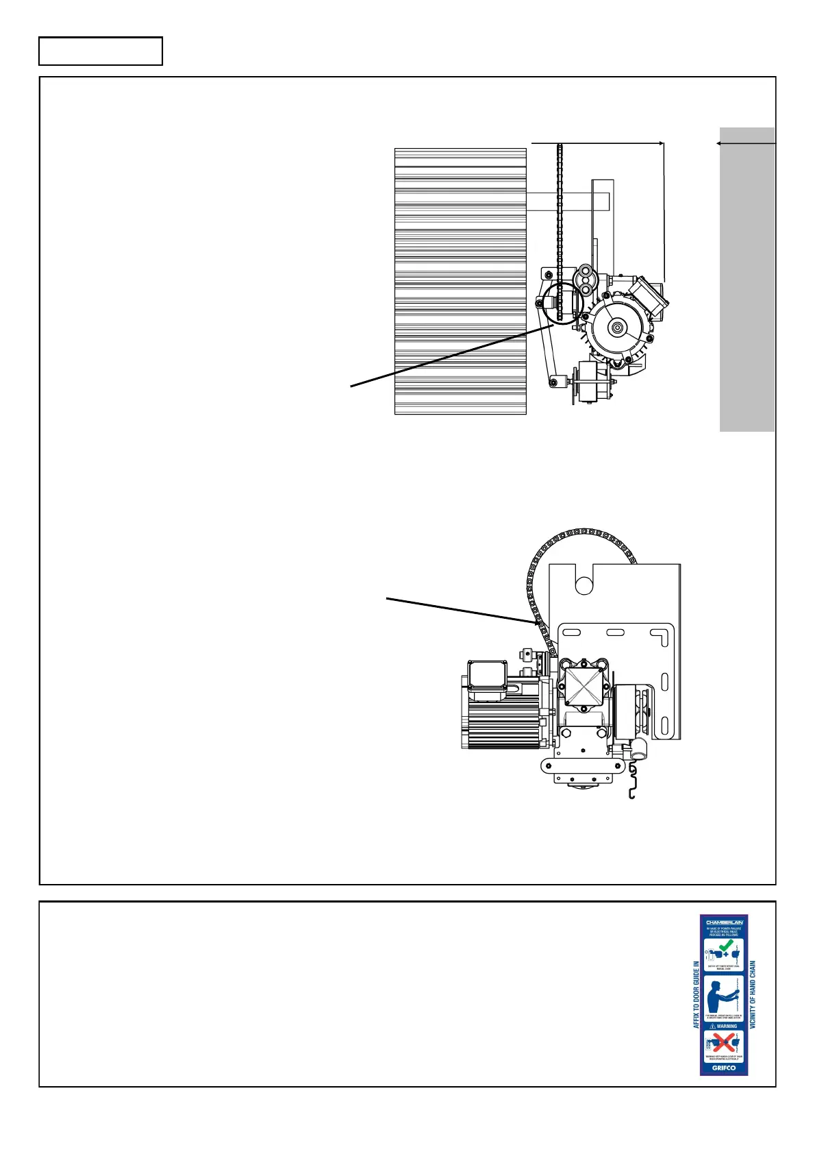
Side room to imposing structures (see right)
Note: The Fire Shuer limit housing requires
adequate clearance to allow seng of limit cams
during installaon. 150mm is the minimum
recommended clearance between wall and lid.
Where there is insucient side room, consider using
the opposite hand opener and mount inboard with a
Grifco
™
Inboard Mounng Kit, Part No. IBMK.
Ensure the mounng posion allows the hand chain to
hang free of obstrucons (see right)
Ensure hand chain is not twisted when making the
join!
150mm Minimum
The drive sprocket must be aligned with the door
sprocket, and locked using 2 x M8 hi-tensile grub
screws ghtened to min 20Nm. Grub screws must be
set between 90˚ and 120˚ apart, with one grub screw
lying over the drive key.
Chain tension should be set between 10-20kgs, ensuring
both sides of the linkage are taught. Where praccable, use
the weight of the opener as a preload, then ghten
mounng bolts. M12 fasteners should be ghtened
between 80-90Nm.
INSTALLATION
Automac Chain Engagement Mechanism (ACEM)
The patented ACEM features allows the use of the hand chain in the event of a power failure. Simply pull on the
hand chain in either direcon to operate the door manually.
Warning! Ensure power is isolated when using this feature.
The ACEM label (see right) must be xed in close proximity to the controller e.g. on the door track.