7
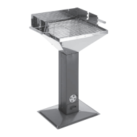
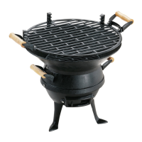
Part list
A. Grill element with two handles 1
B. Charcoal grate 1
C. Wind screen, rear 1
D. Wind screen, right 1
E. Ventilation controller 1
(already mounted)
F. Base 1
G. Ash box 1
H. Column (already mounted) 1
I. Hopper side 4
J. Wind screen, left 1
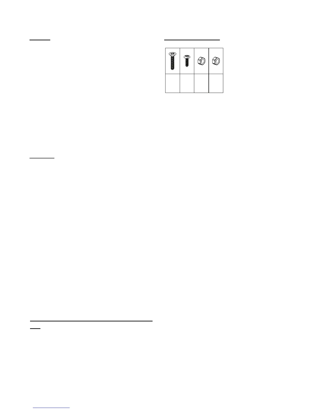
Connecting elements
Assembly
1. Use M5x35 screws and M5 nuts to x the column (H)
on the base (F). Approaching from the top, guide the
screws through the column (H) and into the base (F)!
Make sure the cut-out for the ash box (G) points
forward. (as shown in the drawing)
2. Connect the hopper sides (I) with one another using
M5x12 screws and M5 nuts. For safety reasons, the
screw ends should point into the hopper.
3. Place the assembled hopper (I) onto the column (H).
Screw the parts together using M5x12 screws and
M5 nuts.
4. Mount the wind screen parts (C, D, J) to the outside
of the edges on the hopper sides (I). Follow the
arrangement shown in the drawing. Start with part
"C."
5. Slide the ash box (G) into the bottom of the column
(H).
6. Place the charcoal grate (B) in the hopper.
7. Insert the grill element (A) with the two handles
into the wind screen (C, D, J).
The grill must be in a stable position on a rm substrate
during operation.
Do not use in enclosed areas, or in areas covered by
a roof!
Only use safe lighting materials (such as LANDMANN
solid re starter).
The fuel container has a holding capacity of approximately
2 kg.
Prior to using for the rst time, the grill must be heated for
approximately 30 minutes.
Instructions for safe operation of the grill de-
vice
M5x12
21x
M5
21x
M6
4x
M6x10
4x