Coffee Urns Cecilware
®
5
Installation
Unpacking Instructions
Carefully unpack the machine and inspect immediately
for shipping damage. The packaging may contain
unattached parts. Your machine was shipped in a carton
designed to give it maximum protection in normal
handling. It was thoroughly inspected before leaving
the factory. In case of damage, contact the shipper, not
Grindmaster-Cecilware.
NOTICE: The person installing this appliance is
responsible for ensuring that electric and water
connections meet the requirements of the national
electric code, national plumbing code, and any local
ordinances.
See Rough-in Drawings for approximate dimensions
and locations of electric and water input.
Mechanical Installation
NOTICE: Do not turn thermostat on until all
installation instructions have been followed.
1. Inspect unit to see if any damage occurred in
shipment.
2. Remove the urn from the packing material. The
four legs, faucets, and vent cap drain are packed
separately with urn.
3. Install legs by tilting urn on its side and screwing
legs into urn leg supports until hand tight.
4. Carefully right unit and install in its permanent
location, being sure to leave at least 6" on right side
of urn for access to controls. Position urn so that the
faucets drip into a drip trough or drain receptacle
of some type.
5. Level urn by adjusting legs. Then attach faucets and
install vent cap drain.
6. Cover(s) are shipped with knob(s) on inside to
prevent damage. Simply unscrew and reverse.
WARNING: ELECTRIC SHOCK HAZARD!
Installation of this appliance should be performed by
qualified service personnel only. Improper installation
could result in electrocution.
CAUTION
These urns are heavy pieces of equipment. It is
recommended that moving or lifting the unit be done
by two people to avoid injury.
Neutral and Ground Wires # 14 AWG min.
Note: Field wiring must be suitable for 75° C. Use copper wire only for power supply connections.
GROUNDING: ON ALL URNS, CONNECT A GROUND WIRE TO GROUNDING LUG TO COMPLY WITH LOCAL
ELECTRICAL CODES (14 AWG MIN. 75° C)
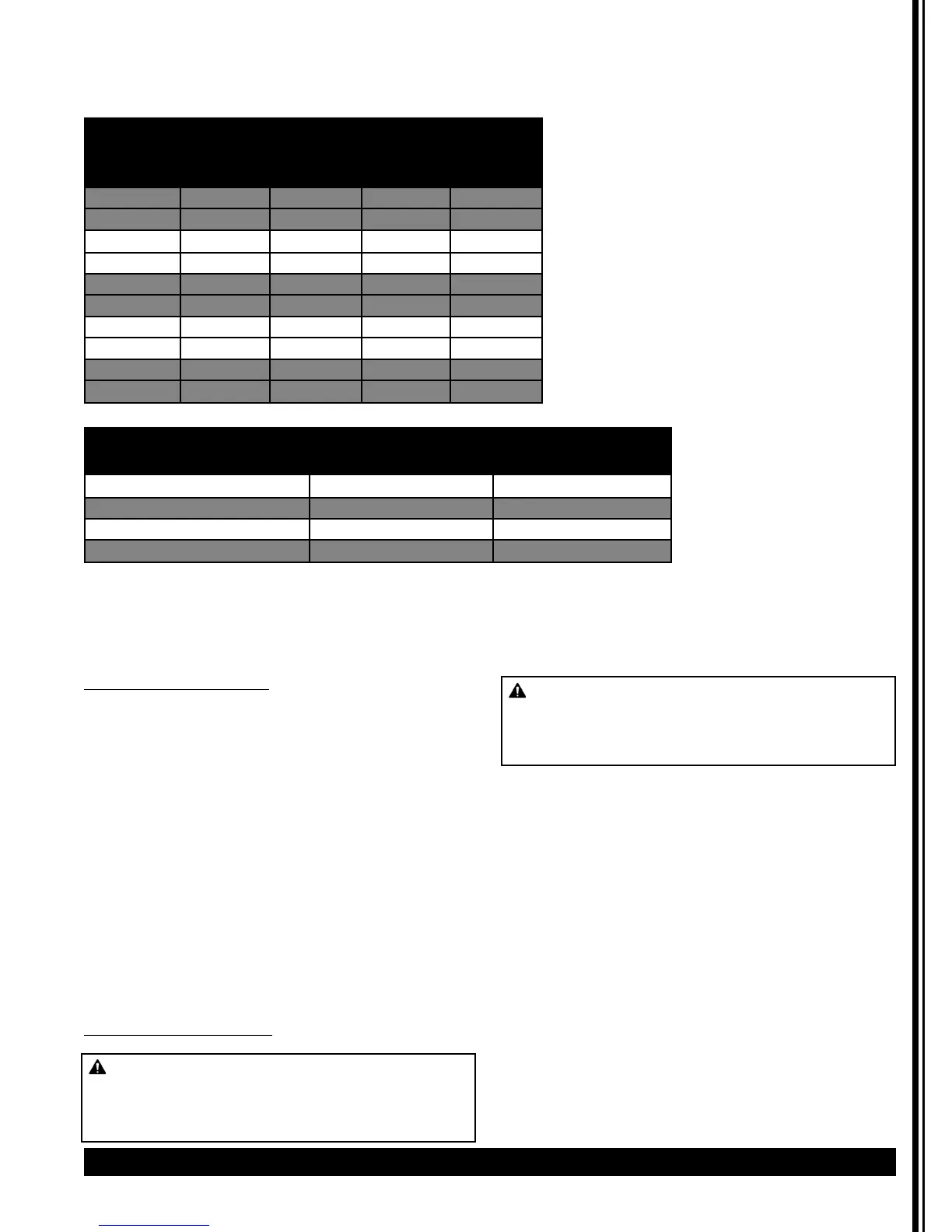
Recommended Wire Size For Field-Wiring Urns US models only. Consult factory for export model information..
Electrical Specifications
Information below provided for US models only. Check rating marking on urn nameplate. Consult factory for
export model information.
VOLTS KILOWATTS AMPS
1 PHASE 3 PHASE 1 PHASE 3 PHASE
3 WIRE 4 WIRE
120/240 7 6 29 15
120/208 5.3 4.5 26 12
120/240 6 8 34 20
120/208 8 6 29 17
120/240 7 8 29 20
120/208 5.3 6 26 17
120/240 10 10 42 24
120/208 7.5 7.5 38 22
120/240 - 15 - 37
120/208 - 11.3 - 33
MODEL WIRE SIZE
1 PHASE 3 PHASE
FE75N, CL75N, CL100N (2) 10 AWG + GND (3) 10 AWG + GND
FE100-N (2) 8 AWG + GND (3) 8 AWG + GND
FE200-N, CL200-N (2) 6 AWG + GND (3) 8 AWG + GND
FE300-N - (3) 10 AWG + GND
 Loading...