Error diagnosis
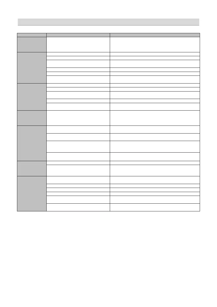
No function PWR LED on?
-check the remote wire
-check the +12 Volt connection and wire
-check the ground connection and wire
No sound
(PWR LED on)
signal wire no contact or broken
-check the contact or replace the wire
no audio signal from the head-unit
-check the audio output signal of the head-unit
amplifier not switched on
-check the remote out of the DSP (page 5)
-check the amplifiers power supply
non operational source selected
-check the setting (page15)
activated >MUTE< function (User Interface)
-check the setting (page15)
adjusted level on optional remote control
unit too low
-check the setting (page7)
Single channels
with no function
signal wire no contact or broken
-check the contact or replace the wire
no audio signal from the head-unit
-check the audio output signal of the head-unit
balance or fader control of the head-unit not
in center position
-check the setting of the head-unit
wrong setup of input and output mode
-check the setting (pages 11~14)
>GAIN< level too low or >Mute< function
(user interface) active
-check the setting (page 15)
Impure sound,
incorrect stereo
reproduction
inverted phase of one or more speakers
-check the polarity of the speaker connection
-check the polarity of the high-level input (page 6)
-check the >PHASE< setting (page 15)
-check the >TIME ALIGNMENT< adjustment (page 16)
Distorted sound
quality
speaker overload
-reduce the volume level
-check the highpass filter and slope (page 15)
DSP input override (distortion)
-select the correct input mode
-pay attention to the input sensitivity of the DSP unit (page 18)
head-unit output override (distortion)
-reduce the volume level of the head-unit
-set the sound controls of the head-unit to center position
-deactivate the >Loudness< function of the head-unit
amplifier override (clipping)
-check the amplifiers input sensitivity
-reduce the level
Increased
noise level
-reduce the >GAIN< level (page 15)
head-unit creates noise
-select a superior quality head-unit
-use the optical output (if available)
-let the audio store or manufacturer check the head-unit
Car specific
interferences
audible through
the audio system
diverse power supplies or ground connection
-the head-unit, the DSP and each amplifier should be wired up to
a common ground and +12 Volt connection
signal wire no contact or broken
-check the contact or replace the wire
-let the audio store or manufacturer check the head-unit
-let the audio store or manufacturer check the amplifier
DSP unit or amplifier mounted close to an
automotive control unit
-choose another mounting position
analog output of an OEM MOST head-unit
connected
-connect the digital MOST audio signal directly to the DSP unit*
*Note: Use an optional car specific interface to connect the digital MOST audio signal directly
to the digital input of the GZDSP 6-8X