Gain setting
Time alignment
Phase control
Click to highlight the channels creating a group for common adjustments.
Level adjustment using the arrows up to required value (max=0)
Time alignment for each channel using the arrows. The value can be
edited directly, as well. It´s recommended editing the real distance from the listening
point to the according speaker prior to the adjustment of the
in detail
Clicking the phase buttons inverts the channel´s phase
Highlighting the function button mutes the channel
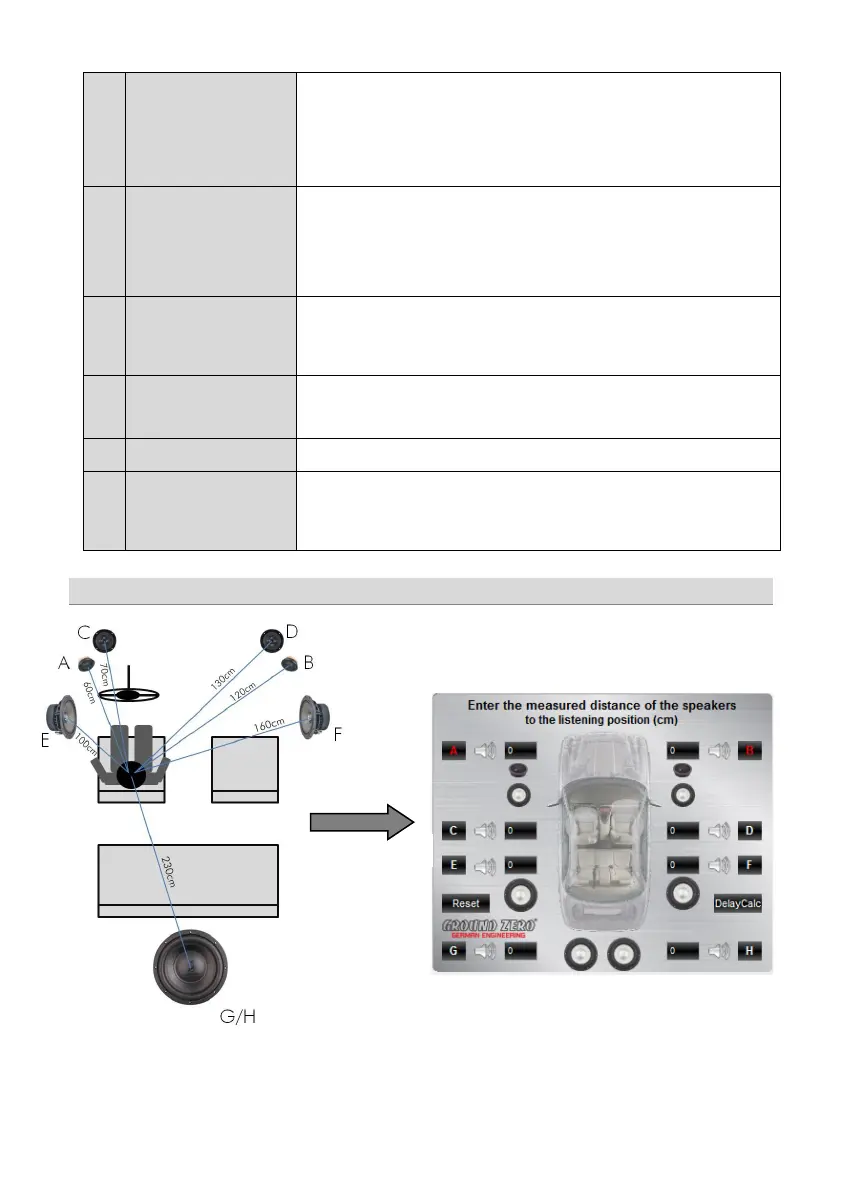
Editing the speaker distance for the time alignment:
Prior to the detailed setting of the time alignment (point 4), all measured distances of
the connected speakers should be edited. Measure the exact distance between the
listening position (head) to the center of the speaker. The according time alignment is
continuously calculated automatically. The calculated alignment values can be
adjusted in detail (check example below). The
Reset
function deletes the time
alignment setting. Further adjustments remain unchanged.
Prior to the filter selection it´s required to set a speaker type (point 3). In order to use
both, the high pass and the low pass filter (bandpass configuration) select
The according slope of the crossover can be set at the dropdown menu between 6
and 48 dB/oct.
The higher the value of the slope, the steeper the roll-off of the
signal (reduction of the level)
Use the sliders to adjust the crossover point between 20 and 20000 Hz. activate the
crossover filter, first (point 6). The value can be edited directly, as well or be changed
at the frequency chart by keeping the yellow or turquoise button clicked and moved
to the desired frequency point at the chart
The frequency chart shows the estimated response of the 31-band equalizer (point 9)
and the crossover adjustments (point 7) of the selected channel (or pair of channels)
The level of each equalizer band can be adjusted to the desired dB value using the
slider. Additionally, the Q of the filter can be selected. Use the arrow buttons or edit
the value directly. By clicking >Bypass< the equalizer will be deactivated without
deleting the setting. >Restore< activates the equalizer again. >Reset< deletes the
Time alignment setting (example)
All measured distances (cm) must be added to the graphic. The
according alignment values will be continuously calculated and
transferred to the
Delay(ms) list to be adjusted in detail if necessary.