Commissioning Instructions
SCS_BA_EV-301_601_EN_12 groupscs.co.uk Date: 31.05.2023
info@groupscs.co.uk Issue: 1.2 / 06.2023
Page 20
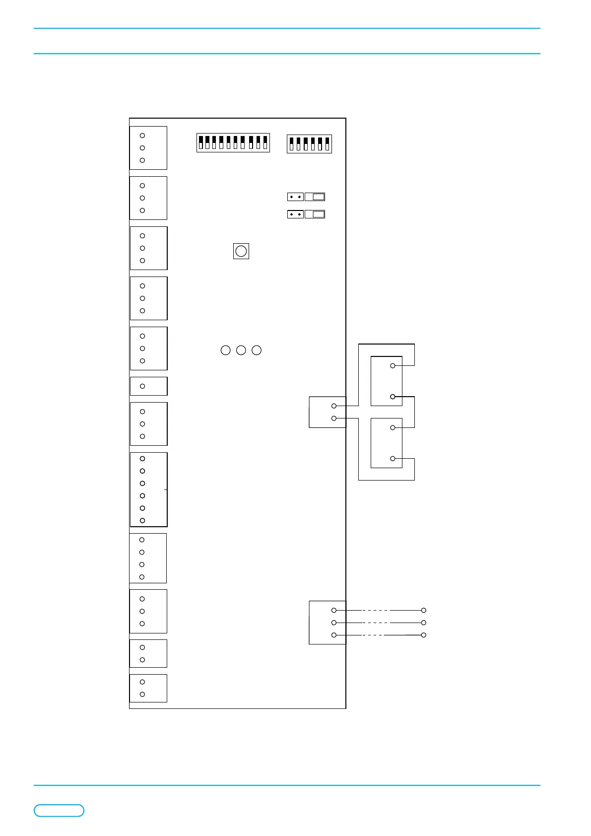
8.3. Wiring Diagrams
Figure 6: Overviewconnectors/DIP-switches/jumpers(simpliedrepresentation)
Reset
Alarm
LED OK
LED Alarm
LED Fault
LEDs only under mains operation
L1
NPE
+
–
L1
NPE
+
–
Battery
+
–
Battery
Battery Connection
Mains Connection –
pole disconnecting
main switch on site (L1, N)
Head of Shaft / Stair Panel / Shaft Panel
765
NO NCC
B1
S1
8
9
10
11
A1
–
1 2
24V
–
3 4
+
–
12 13
14
15
17
16
E
–
ES LZ Z A
20
19
18
OGS
21
F
24
23
22
OGS
272625
A2
B2
–
302928
A3
B3
–
363534
B
SG
A
333231
B
SG
A
1
2
3
4
6
SW1
ON
OFF
55
1
2
3
4
6
7
8
9
10
SW2
55
DATA BUS
Contact
FAS 2
Fire Alarm
Motor 1 Motor 2
Motorchannels T3.15A (EV-301)
Motorchannels 6.3A (EV-601)
Emergency
Button
FAS 1
Smoke Detector
Inputs
Wind/Rain Vent Switch
Analog
IN
Backup
Addressing (1 – 8)
Functions
Jumpers
2 1
BAT
MODE
JP1
ONOFF
SPEV
ON
OFF
 Loading...