Commissioning Instructions
SCS_BA_EV-301_601_EN_12 groupscs.co.uk Date: 31.05.2023
info@groupscs.co.uk Issue: 1.2 / 06.2023
Page 24
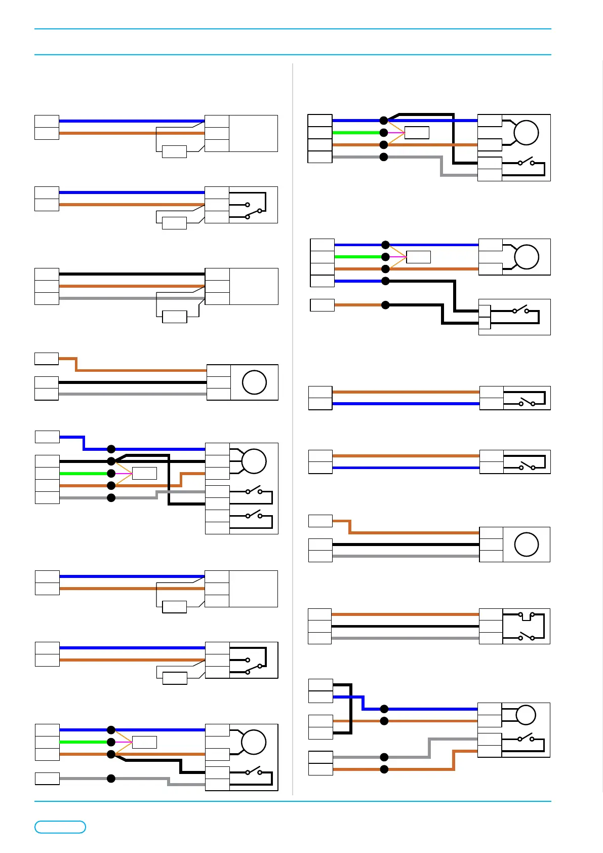
8.5.2. Wiring details EV-Mode
Figure 17: Smoke Detectors
-
B2 IN+
Smoke Detector
FAS1
COM-
OUT+
27KΩ
Figure 18: Fire Alarm Interface
-
B2 NO
COM
NC
27KΩ
Figure 19: Override Switches
S1
B1 B1
Override Switch
Switch
S1
--
27KΩ
Figure 20: Stair Door Pressure Sensor
ES
- -
EV-PS100
Pressure Sensor
Inputs
+
+ V
Analog
0-10V
Figure 21: Smoke Damper
-
S
O
3
2
Shaft Damper
24VDC Belimo
Backup
1
M
S1
S2
F
G
S4
S6
EOL
JB
Motor 1
Closed
Open
Figure 22: Smoke Detectors – Reverse Fans
-
B3 IN+
Smoke Detector
FAS2
COM-
OUT+
27KΩ
Figure 23: Fire Alarm Interface – Reverse Fans
-
B3 NO
COM
NC
27KΩ
Figure 24: Door Opener
S
O 2
24VDC Rev Polarity
1
M
C1
C2
Z
G EOL
JB
Motor 2
Open
Inputs
Figure 25: AOV/WindowActutator
S
O 2
AOV Window Actuator
24VDC Rev Polarity
1
M
C1
C2
F
G EOL
JB
Motor 1
Closed
Figure 26: Head of Stair Vent
S
O 2
Head of Stair Vent
Head of Shaft Vent
24VDC Rev Polarity
1
M
E
G EOL
JB
Motor 1
Closed
EV-VPS
Vent Position Switch
F
Inputs
Figure 27: Head of Stair Vent Maintenance Access Switch
E
Z
Open
EV-FOSMKS
Maintenance
Access Switch
Inputs
Com
Figure 28: Thermostat
E
A Y2
EV-ITH
Thermostat in EV mode
Inputs
L
Figure 29: Temperature Sensor
ES
- G0
EV-ITS
Temperature Sensor
G
+
U1
Analog
0-10V
Figure 30: Wind/RainSensor
ES
-
LZ
Inputs
5
(Wind) Rain Sensor
1
2
Figure 31: Daily Damper
-
NO
2
Daily Damper
24VDC Spring Close
1
M
S1
S2
C
24V
JB
LZ
E
Contact
Inputs
Closed
 Loading...