20 21
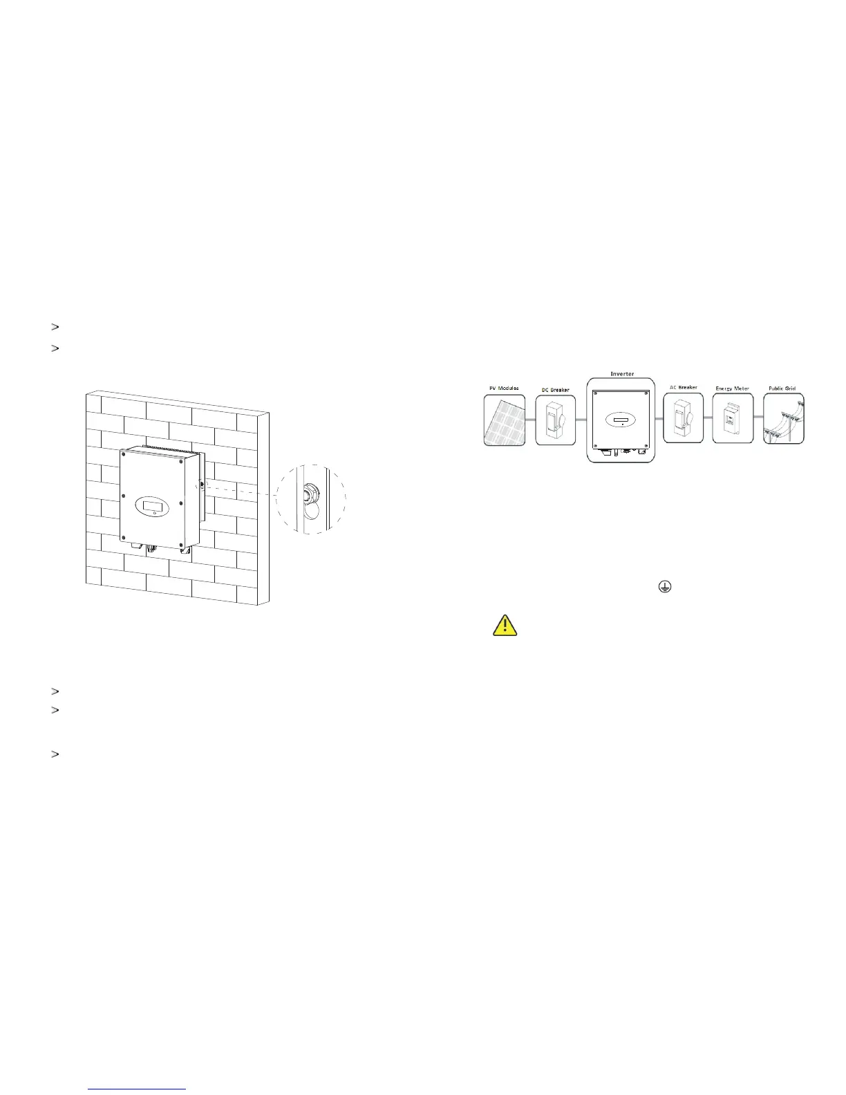
5.3.2. Mounting Inverter
Connecting the Second Protective Conductor
If the installation requires, the earth terminal can be used to connect a second
protective conductor or as equipotential bonding. This prevents touch current
if the original protective conductor fails.
Cable requirement:
Earthing cable cross-section: 3.332 mm² at maximum
5.4. Connect switch
Separate the Growatt inverter securely from the grid and the PV generators using
DC and AC Switch. You must provide an AC circuit breaker. If Growatt DC Switch
is included in the delivery of the Growatt inverter, it must be used for operating the
inverter.
5.5. Grounding
The Growatt 750-S-3000-S series are transformerless inverters. That is why it has
no galvanic separation. Do not ground the DC circuits of the PV modules
connected to the inverter. Only ground the mounting frame of the PV modules. If
you connect grounded modules to the inverter, the error message "PV ISO Low".
The inverter must be connected to the AC grounding conductor of the power
distribution grid via the ground terminal (PE)
WARNING
Because of the transformerless design, the DC positive pole and
DC negative pole of PV arrays are not permitted to be grounded.
5.6. Connect grid type
TN-C grid suitable
TN-S grid suitable
TN-C-S grid suitable
TT grid suitable
Referring to the following figure, make the inverter and explosion screw
matching,
Hang the inverter on the explosion screw
 Loading...