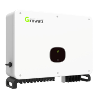
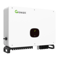
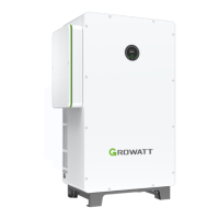
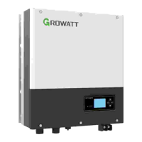
4 Unpacking
Checking before installation
1>Before unpacking the inverter, check the outer packing materials for damage.
2>After unpacking the inverter, check that the contents are intact and complete. If any
damage is found or any component is missing, contact your supplier.
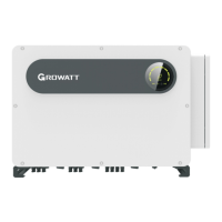
Package contents:
Installation 5
5.1 Basic Installation Requirements
A. Ensure that the installation wall is solid enough to bear the inverter(Inverter weight
please refer to installation manual Chapter3, 3.2 ).
B. There must be enough installation space to fit the size of inverter.
C. Do not install inverter on flammable or heat-intolerant buildings.
D. This inverter is IP 66 protection, you can install it indoor or outdoor.
E. To avoid inverter performance de-rate due to the over heat, please do not expose the
inverter under direct sunlight.
F. The installation humidity should be from 0-95%.
G. The surrounding temperature of inverter should be from -30℃ - +60℃.
H. Inverter should be installed in a vertically or rear tilted surface, please refer to
following drawings.
Fig 5.1
I. To ensure the inverter can work smoothly and easy for personnel to operate, please
notice there is sufficient space for inverter, refer to following drawing.
Fig 5.2
10
9
•To prevent device damage and personal injury, keep balance when
moving the inverter because it is heavy.
•Do not place the inverter with its wiring and signal terminals at the
bottom contacting with floor or any other object because the terminals
are not designed to support the weight of inverter.
•When placing inverter on the floor, put foam or paper under the inverter
to protect its cover.
CAUTION
A B C D E
F G H I
J
K L
Fig 4.1
PV + terminal, PV- terminal
Removal tool of PV terminals
M6*28 stainless steel screw
AC wiring copper terminal (opt)
≥
6
0
0
m
m
≥
6
0
0
m
m
≥
6
0
0
m
m
≥
6
0
0
m
m
≥
1
0
0
0
m
m
 Loading...


