EasyManuals Logo

Growatt MAX Series Manual

Growatt MAX Series
6 pages
To Next Page IconTo Next Page
To Previous Page IconTo Previous Page
Page #5 background imageLoading...
Page #5 background image
4. Turn on the system
After configure the inverter setting, turn on DC switch, inverter will begin to work.
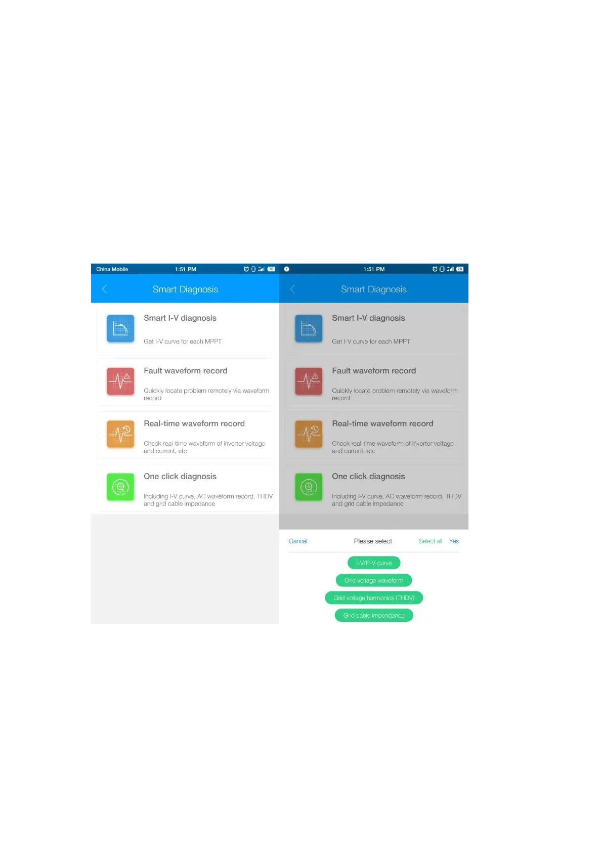
You can check the system information of the inverter via Growatt ShinePhone.
Click Smart Diagnosis to the diagnosis page, use One click diagnosis can check
the I-V/P-V curve, grid voltage waveform, grid harmonic, grid impendence at one
time, it will takes around 10 min.
Also you can only select one to check the information, such as I-V curve, AC voltage
waveform. The fault waveform record function is only used by guide of Growatt
engineers when necessary.
Back to the Local debugging tool homepage, click Device information, you can
check the inverter parameters, PV string data, AC grid data, inverter information and
so on.

Other manuals for Growatt MAX Series

Questions and Answers:

Question and Answer IconNeed help?

Do you have a question about the Growatt MAX Series and is the answer not in the manual?

Growatt MAX Series Specifications

General IconGeneral
Max. DC Voltage1100 V
MPPT Voltage Range200-1000 V
Number of DC Inputs per MPPT2
Nominal Grid Frequency50/60 Hz
THDi<3%
DC SwitchYes
MPPTYes
CommunicationWiFi, GPRS, Ethernet
Nominal AC Voltage400 V
AC Voltage Range310-480 V
Power Factor0.8 leading ... 0.8 lagging
Operating Temperature Range-25°C to +60°C

Related product manuals