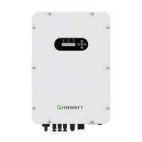
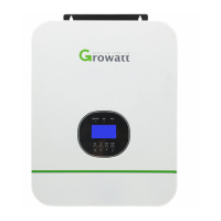
This document describes the Growatt Solar Pump Inverter, a device designed to convert DC power from solar panels into AC power to operate various types of pumps. This series of inverters ranges from 3000W to 22000W and is specifically designed for three-phase 380V solar pump systems.
Function Description
The core function of the Solar Pump Inverter is to facilitate the operation of pumps using solar energy. It acts as an intermediary, taking direct current (DC) generated by solar panels and transforming it into alternating current (AC) suitable for powering three-phase asynchronous motors found in submersible pumps, ground pumps, and swimming pool pumps. A key integrated feature is the Maximum Power Point Tracking (MPPT) solar charger, which optimizes the power extraction from the solar panels, ensuring maximum efficiency and output for the pump system. The inverter is equipped with comprehensive protection mechanisms and self-diagnosis capabilities to ensure reliable and safe operation.
Usage Features
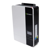
The inverter offers a user-friendly interface with an LCD display and LED indicators, providing real-time system status. There are three LED indicators: POWER (green, indicating the inverter is running), ALARM (yellow, for warnings or auto-operation mode flashing), and FAULT (red, indicating a system failure). The LCD display provides various information including operation data, control parameters, and historical parameters, which can be navigated using UP/DOWN keys.
The device supports multiple work modes:
- Manual Work Mode: Allows for direct control and adjustment of parameters.
- Fully-Automatic Terminal Work Mode: The default mode, enabling automated operation based on pre-set conditions.
- GPRS Work Mode (Optional): Facilitates remote monitoring and control, providing flexibility for managing the pump system from a distance.
Installation and Wiring:
Installation requires careful consideration of the environment. The inverter should be mounted on a solid, non-combustible metal surface, away from direct sunlight, in a shady and cool environment. It is recommended to install the inverter in a waterproof and dustproof box at eye level for easy LCD readability. Sufficient space around the unit (at least 100cm on top and sides, 300cm at the bottom) is necessary for heat dissipation and wiring access.
Wiring involves connecting DC input from solar panels, AC output to the pump, and water level sensors. The manual provides detailed instructions for assembling DC and AC connectors, emphasizing the importance of firm connections and avoiding short circuits. For AC connections, four wires (U, V, W, and PE) are used to connect to the pump. If the cable between the inverter and water pump exceeds 50m, a three-phase AC reactor (approx. 1mH inductance per phase) is recommended to prevent pump damage.
Water Level Sensor Integration:
The inverter supports water level sensors to prevent dry running and overfilling.
- Water Level Sensor 1 (Well): Detects water shortage in the well. If the water level drops below a set threshold, the inverter will delay for 60 seconds before turning off the pump to protect it. Once the water level recovers, the inverter waits for 600 seconds before restarting.
- Water Level Sensor 2 (Tank): Detects when the water tank is full. If the water level exceeds the set threshold, the inverter delays for 60 seconds and then turns off the pump. When the water level drops below the set level, the inverter waits for 120 seconds before restarting.
Parameter Setting:
The inverter allows for various parameter settings to optimize performance. Key parameters include:
- P00.01 (Run Command Model): Selects the work mode (manual, auto, or communication).
- P00.03 (MAX. Output Frequency): Sets the maximum output frequency of the inverter.
- P00.04 (Upper Limit of Running Frequency): Defines the upper limit of the inverter's running frequency.
- P00.05 (Lower Limit of Running Frequency): If solar energy is insufficient, the inverter will reduce frequency; if it drops below this limit, the inverter stops.
- P00.13 (Set Direction): Controls the motor's rotation direction (forward, reverse, or forbidden).
- P02.01-P02.05 (Motor Nameplate Parameters): Allows input of the motor's rated power, frequency, voltage, and current for accurate control.
- P15.00 (PV Inverter Selection): Enables or disables the MPPT function.
- P15.04/P15.05 (PID Max/Min Output Frequency): Limits the target frequency range for PID control.
- P15.13 (Delay Time of Dry-Water): Sets the delay for dry-water protection.
- P15.14 (Wake-up Delay Time of Dry-Water): Sets the recovery time after dry-water shutdown.
- P15.15 (Automatic Dry Run Protection): Configures automatic dry run protection based on current and frequency thresholds.
- P15.16 (Delay Time of Full-Water): Sets the delay for full-water shutdown.
- P15.18 (Reset Delay of Full-Water): Sets the recovery time after full-water shutdown.
- P15.19 (Frequency of Weak Light): Sets the frequency threshold below which the inverter stops due to weak light.
- P15.20 (Delay Time of Weak Light): Sets the delay for weak light shutdown.
- F15.21 (Reset Delay of Weak Light): Sets the recovery time after weak light shutdown.
Maintenance Features
The inverter is designed with self-diagnosis and protection features to minimize the need for frequent manual intervention. However, certain maintenance aspects are crucial for its longevity and safe operation.
Safety During Maintenance:
Only qualified personnel should perform maintenance, repair, or inspection of the inverter and replace components. Before any service, it is critical to disconnect all power sources (PV terminal and AC terminal) and wait at least 5 minutes to allow internal capacitors to discharge, ensuring the bus voltage is within a safe range. This prevents electric shock.
Troubleshooting and Protection:
The inverter incorporates comprehensive protection mechanisms. In case of a failure, it will automatically take protective measures, typically stopping the motor and preventing restarts for a specified period. The manual provides a detailed troubleshooting guide for various fault codes, including:
- Power off (No failure): Indicates no specific fault.
- Inc OVP/Dec OVP/Const OVP (Overvoltage): Possible causes include high input voltage or large energy feedback. Solutions involve checking solar array voltage and load deceleration time.
- Bus low (Undervoltage): Caused by low input voltage or weak illumination. Solution is to check solar array voltage.
- Inc OCP/Dec OCP/Const OCP (Overcurrent): Can be due to an oversized pump, low solar array voltage, long motor wiring, insufficient inverter power, or short-circuited/phase-loss grounding. Solutions range from replacing the pump to checking wiring and selecting a larger inverter.
- Overload Pump (Water pump is overload): Often caused by incorrect motor rated current settings, low input voltage, improper overload protection threshold, or motor block. Solutions include resetting motor current, inspecting power supply, and adjusting torque boost.
- Overload VF (Inverter is overload): May result from short acceleration time, restarting a rotating motor, low input voltage, or heavy load. Solutions involve increasing acceleration time, avoiding restarts, checking power supply, and selecting a larger capacity inverter.
- IGBT short (Module overcurrent): Indicates a short circuit or grounding module damage. Requires checking wiring and seeking after-sales support.
- Inv Overtemp/Rec Overtemp (Module is over-temperature): Possible causes include blocked air vents, high ambient temperature, prolonged overload running, or control board abnormalities. Solutions include cleaning air vents, improving ventilation, and selecting a proper motor.
- Phase out loss (Output default phase): Indicates phase loss in U, V, W output or severe unbalance in three-phase input. Requires checking output distribution, motor, and cable.
- Shortcut GND 1 (Grounding short circuit): The output line may be connected to ground. Solution is to check the wiring.
- Curr fault (Current detection failure): Can be due to poor control board connection, damaged hall component, or abnormal magnifying circuit. Solutions involve checking/rewiring connectors and replacing components if necessary.
- Lack load when set dry-power (P15.15) is not 0.0% (Water pump conducts "dry-operation"): Caused by open circuit in water pump connection wires or lack of water sources. Solutions include checking P15.15 parameter, pump wiring, and inverter capacity.
- Lack Water (Water shortage): Triggers a water shortage warning. If the alarm function is enabled, the device stops automatically; otherwise, check for misconnected terminals.
- Water Full (Water full): Triggers a water full warning. If the alarm function is enabled, the device stops automatically; otherwise, check for misconnected terminals.
- Com Fault (Communication failure): Indicates device or circuit damage. Requires a reset or after-sales support.
Factory Data Reset:
The inverter allows for a factory data reset (P00.18) to restore default settings, which can be useful for resolving complex issues or reconfiguring the device. However, it's crucial to identify the root cause of any failure before continuously resetting, as repeated resets can potentially damage the inverter.
Soft Start Function:
The inverter includes a soft start function, which gradually increases the motor speed upon startup. This reduces mechanical stress on the pump and motor, extends their lifespan, and minimizes inrush current, contributing to overall system reliability.
Remote Monitoring (Optional):
For enhanced convenience and management, the inverter offers remote monitoring capabilities through GPRS or Wi-Fi modules (optional). This allows users to track system performance, receive alerts, and potentially adjust settings from a remote location, improving operational efficiency and responsiveness.