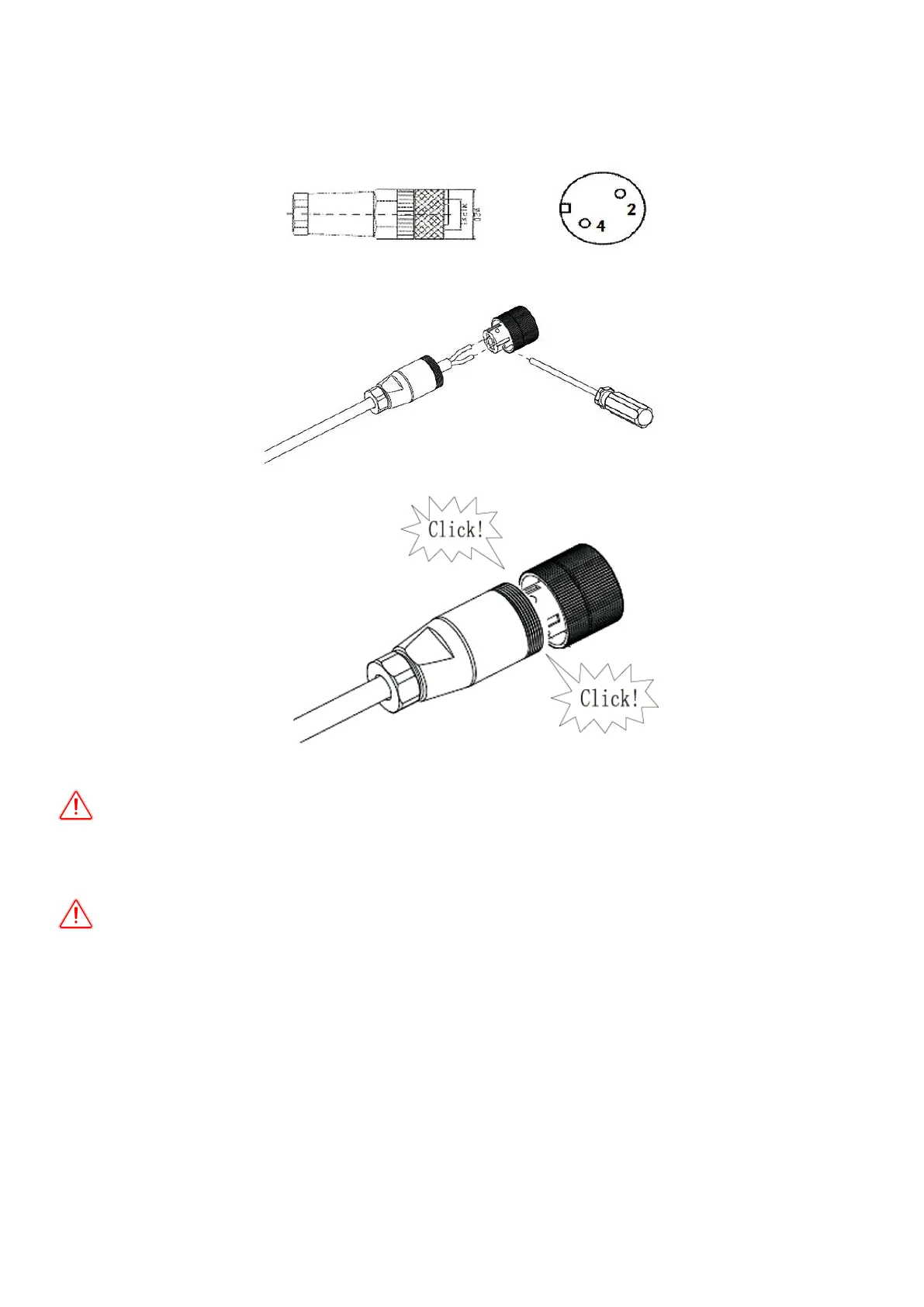
Assemble Sensor connector
Insert the stripped and bared conductors 2,4 in to screw termianls signal 2,4 on the socket element and tighten the
screws.
Push the threaded sleeve in to the socket element. Screw the pressue screw thightly onto the threaded sleeve.
Notice: connect water level sensor 1 and detect water shortage. Respectively connect two signal lines of sensor
with S4 and COM of I/O circuit board. When water level sensor 1 detects that the water level of well is lower than the
level set by sensor, the pump inverter will delay for 60s, then turn off output protection pump. The water level recovers.
Wait for 600s, then the pump inverter re-works normally.
Notice: connect water level sensor 2 to defect whether water is full. Connect two signal lines of sensor with S2
and COM. When water level sensor 2 detects that the water level of water tank exceeds the level set by sensor, the
pump inverter delays for 60s and turns off output; when water level is lower than set level, wait for 120s, then pump
inverter re-starts to work normally.
 Loading...