27
6.8.3.2The inverter is preconfigured to the following RRCR power levels:
Active power control and reactive power control are enabled separately.
Pin 1
Active power
Cos(φ)
Short circuit
with Pin5
Short circuit
with Pin5
Short circuit
with Pin5
Short circuit
with Pin5
0%
30%
60%
100%
1
1
1
1
6.9 AFCI Optional)(
6.9.1 Arc-Fault Circuit Interrupter (AFCI)
In accordance with the National Electrical Code R, Article 690.11, the inverter has a
system for the recognition of electric arc detection and interruption. An electric arc
with a power of 300 W or greater must be interrupted by the AFCI within the time
specified by UL 1699B. A tripped AFCI can only be reset manually. You can deactivate
the automatic arc fault detection and interruption (AFCI) via a communication product
in "Installer" mode if you do not require the function. The 2011 edition of the National
Electrical Code R, Section 690.11 stipulates that newly installed PV systems attached to
a building must be fitted with a means of detecting and disconnecting serial electric
arcs (AFCI) on the PV side.
6.9.2 Danger information
Danger of fire from electric arc
Only test the AFCI for false tripping in the order described below.
Do not deactivate the AFCI permanently.
If an "Error 200" message is displayed, the buzzer alarms, an electric arc occurred in
the PV system. The AFCI has tripped and the inverter is in permanent shutdown.
28
Pin 2 Pin 3 Pin 4
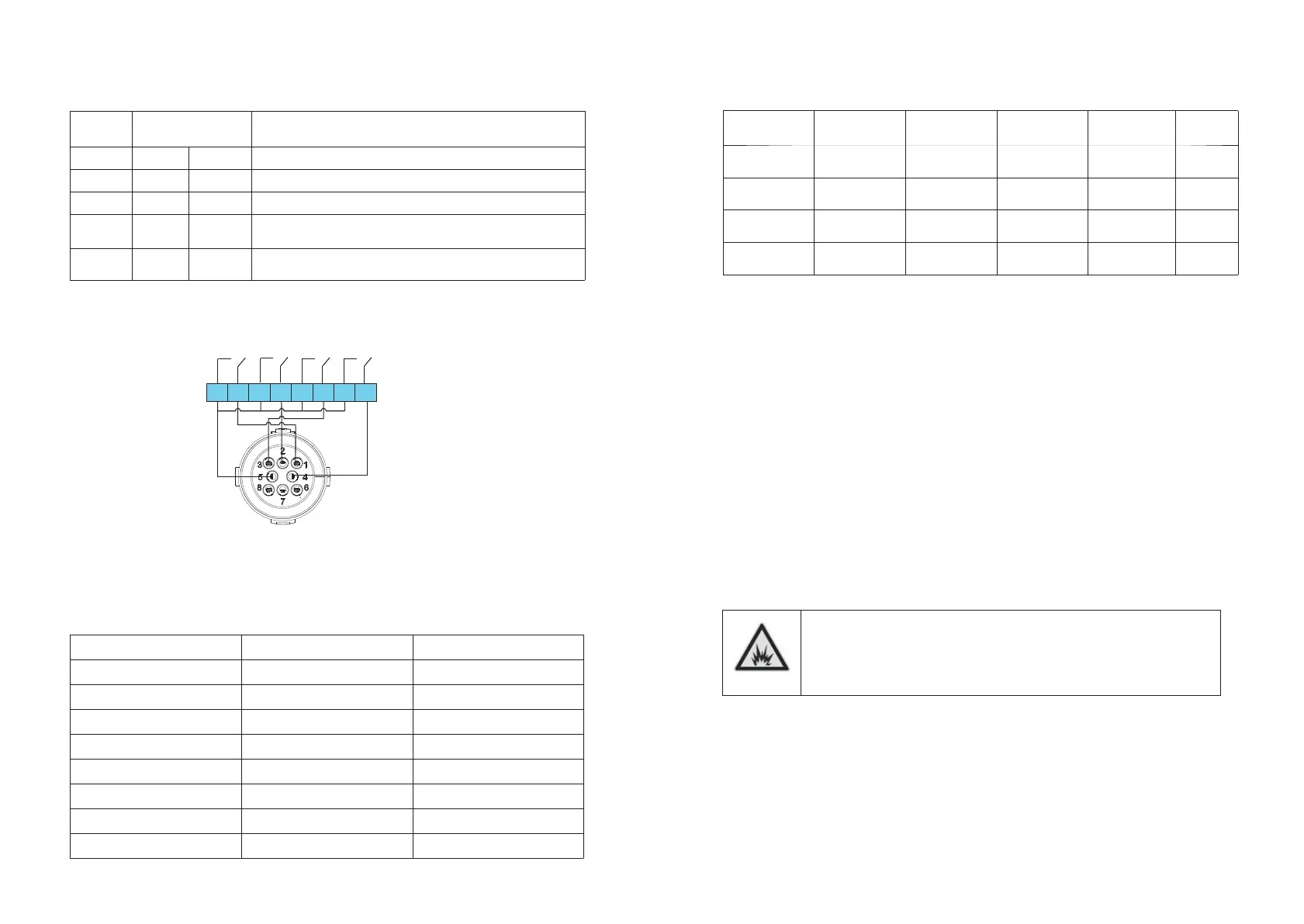
6.8.2 Method of asserting demand response modes
Mode
DRM 0
DRM 5
DRM 6
DRM 7
DRM 8
Function
5
1
2
3
4
6
5
5
5
5
Operate the disconnection device
Do not generate power
Do not generate at more than 50% of rated power
Do not generate at more than 75% of rated power AND
Sink reactive power if capabie
Increase power generation (subject to constraints from
other active DRMs)
Socket Asserted
by shorting pins
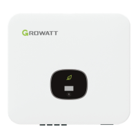
6.8.3 Using the Power Control Interface for EU
6.8.3.1 The following table describes the connector pin assignment and function:
DRM Socket Pin NO. Description
Connect to RRCR
1
2
3
4
5
6
7
8
Not connected
Relay contact 2 input
Relay contact 3 input
Relay contact 4 input
GND
Relay contact 1 input
Not connected
Not connected
Not connected
K2 – Relay 1 output
K3 – Relay 1 output
K4 – Relay 1 output
Relays common node
K1 – Relay 1 output
Not connected
Not connected
Inverter – RRCR Connection
DRM socket
PRCR
 Loading...