21
22
6.3 DC side wiring
Suggested line length:
MOD TL3-X series and MOD TL3-X-AU series
Ø Sunlight will generate voltage on the battery panel.The high voltage
after the series connection may cause life danger.Therefore, before
connecting the DC input cable,you need to cover the battery panel with an
opaque material before operation,and ensure the reverse The DC switch of
the inverter is in the "OFF" state,otherwise the high voltage of the inverter
may cause life danger.
Ø To avoid electric shock,do not touch the live parts,and connect the
terminals carefully.
Ø Please make sure that the AC switch has been disconnected before
wiring.
Please ensure that the following conditions are met, otherwise it may
cause a fire hazard or damage the inverter. In this case, the company
does not carry out quality assurance and assumes any responsibility.
Ø The maximum open circuit voltage of each string of photovoltaic
modules shall not exceed 1100Vdc under any conditions.
Ø PV modules connected in series in each PV string are of the same
specification type.
Ø The maximum short-circuit current of each PV string must not exceed
26A under any conditions.
Ø The total output power of all PV strings must not exceed the maximum
input power of the inverter.
Ø In order to optimize the system configuration,it is recommended to
connect the two inputs with the same number of photovoltaic modules.
Ø If the inverter output is directly connected to the grid (that is, the
o u t p u t s i d e i s n o t c o n n e c t e d t o a l o w - f r e q u e n c y i s o l a t i o n
transformer),please ensure that the PV string is not grounded.
Ø if the inverter input is connected with a specific type of thin-film
battery module (PV-grounded),please connect the low-frequency isolation
transformer to the output terminal before turning it on,otherwise the
inverter will be damaged.
Ø If a stable non- zero DC voltage is measured between the positive
pole of the photovoltaic string and the ground,it means that an
insulation fault has occurred at a certain position in the photovoltaic
string.You need to ensure that the fault is repaired before continuing
the wiring.
Danger
Warning
Note
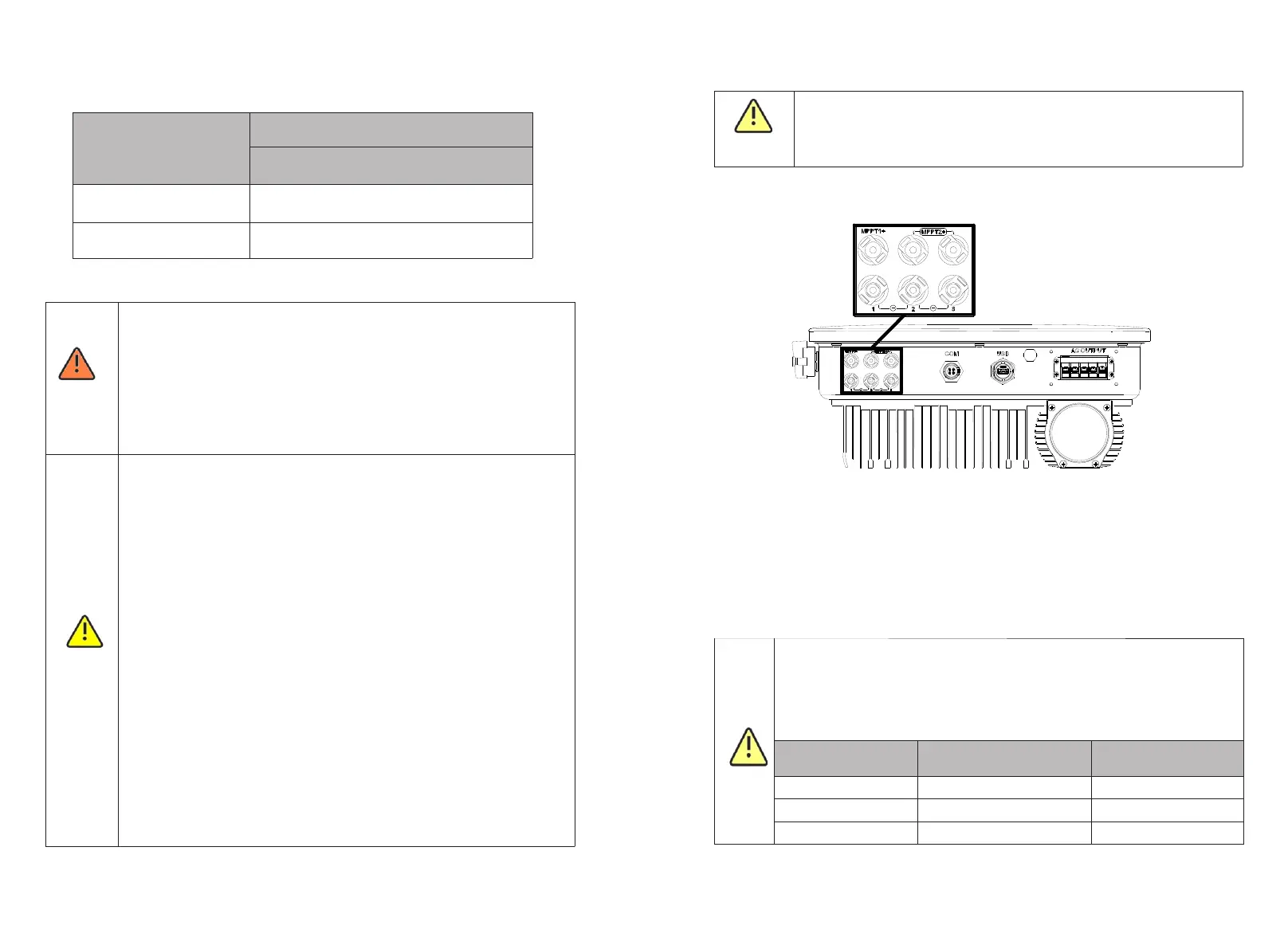
The MOD series inverter has two independent inputs, as shown in the figure below:
Fig 6.11
Note: MOD 3-11KTL3-X (2-channel string); MOD 12-15KTL3-X and 7-11KTL3-X-AU(3-
channel string) .
The following points should be concerned when choosing photovoltaic modules:
Ø The photovoltaic modules of each photovoltaic string are of the same specification
and model.
Ø The photovoltaic modules of each photovoltaic string are connected in series with
the same number.
Ø Before connecting the battery panel, please make sure that the DC input
polarity is correct, that is, the positive pole of the photovoltaic module is
connected to the DC input terminal marked "+" of the inverter, and the
negative pole is connected to the DC input terminal marked "-".
Ø The maximum DC input current and voltage of the inverter shall not
exceed the following limits.
Single maximum input
current
Note
Moisture and dust penetration can damage the inverter.
Ø Make sure that the waterproof cable gland is firmly tightened.
Ø If the cable connector is not installed correctly,the inverter may be
damaged due to the penetration of moisture and dust.All warranty claims
are void.
 Loading...