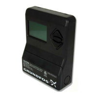
PMU fault indication menu
Press the button on the PMU to see the following faults.
The PMU will keep the last 10 faults in memory.
PMU alarm examples
Alarm type: Zone, Pump,
PFU, System.
Time alarm occurred (hh-mm)
24-hour clock.
Detail of alarm: See chart
below.
Time & date alarm cleared. If
“Actual” then alarm still exists.
Date alarm occurred (dd-mm)
Alarm zone A min. limit
10:12 03-11 10:22 03-11
12
PMU alarm display Condition Possible remedy
Alarm System mains drop
10:12 03-11 11:43 29-10
There was a power failure to the system. This is normal during shipping as there was
a power failure to the system. Simply reset
the alarm.
Alarm Zone A max. limit
10:12 03-11 Actual
High System Pressure on discharge.
Possible VFD failure or max. limit set too low.
Solve VFD problem. Adjust max. limit to higher
value (may be too close to set-point (system
pressure).
Alarm Zone A min. limit
10:12 03-11 Actual
Low System Pressure on discharge. Possible
pipe breakage in system or pipes are not yet
filled.
Repair piping. Adjust Min. Limit to a lower
value as it may be set too high (too close to
system pressure).
Alarm Zone A Watershort
10:12 03-11 Actual
Low Suction Pressure. Check suction condi-
tions.
If inlet is pressurized, lower min. pre-pressure. If
flooded suction or suction lift, ensure water is in
suction piping.
Alarm Zone A speed cont.
10:12 03-11 10:16 03-11
Speed Control (Variable Frequency Drive)
Fault.
Check VFD fault log.
Alarm Zone A sensor AI1
10:12 03-11 Actual
Sensor fault on Analog Input 1 (discharge
pressure transducer)
Check transducer connections (may just be
loose wire). Check transducer. Replace if
necessary.
Alarm Zone A sensor AI2
10:12 03-11 Actual
Sensor fault on Analog Input 2 (normally suc-
tion pressure transducer).
Check transducer connections (may just be
loose wire). Check transducer. Replace if
necessary.
Alarm Zone A sensor AI3
10:12 03-11 Actual
Sensor fault on Analog Input 3 (normally
external set-point).
Check external set-point source. Check con-
nection (may be loose or not connected at
all).
Alarm pump: 1 fault
10:12 03-11 Actual
Fault on pump number 1. If pump is on/off pump (constant speed),
check manual motor protector (breaker). If
pump is MLE or Baldor Smartmotor, check
motor fault log or consult motor Installation
& Operating Instructions. Check voltage moni-
tor relay.
Alarm PFU 123
15:12 03-11 Actual
There is a communication error between
the PMU and the PFU that is connected to
pumps 1, 2 and 3.
Check BUS (RS485) connection between PMU
and
PFU. Check power supply to PFU and/
or PMU. Check fuse in PFU.
 Loading...


