Construction
Grundfos BoosterpaQ systems consist of 1-8 pumps
with all necessary fittings and a Grundfos Control 2000
mounted on a common base frame, ready for installation.
The Control 2000 has its own base for large BoosterpaQs.
In most cases a diaphragm tank must be included in the
installation.
BoosterpaQ Control Modes
BoosterpaQs always include the Grundfos PFU 2000
Controller, but a PMU 2000 can be added. The optional
PMU 2000 provides additional functions and detailed sys-
tem information via a LCD (Liquid Crystal Display).
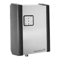
If the BoosterpaQ includes the PFU 2000 only, its faceplate
will be located on the control panel door (see below). If
the BoosterpaQ includes the optional PMU 2000, the PMU
2000 replaces the PFU 2000 faceplate (see below).
4
BoosterpaQs offer the following functions:
• Closed-loop control
• Automatic shut-off at zero flow
• Automatic cascade control of pumps
• Automatic pump rotation to equalize operation time
among the pumps; and with PMU 2000, selectable
pump priority, minimum pump operation, and selec-
table pump sequencing
• Manual operation of each pump
• Possibility of various analog set-point influences:
– friction loss compensation (flow-dependent set-point
control with or without flow measurement), PMU
2000 only
– external set-point adjustment
• Possibility of various digital remote-control functions:
– system on/off
– reduced capacity during emergency power situations
(PMU 2000)
– alternative set-points (PMU 2000)
– switching off individual pumps
• Pump and system monitoring functions:
– minimum and maximum limits of actual value
(high and low system pressure)
– pre-pressure (out of water or low inlet pressure)
– motor protection
– BUS communication (GeniBUS Protocol)
• LCD Display and indication functions:
– 2 x 24 character LCD display (PMU 2000)
– green indicator light for operating indications and red
indicator light for fault indications
– potential-free relay contacts for operation and fault
• Multiple set-points (PMU 2000)
• Grundfos BUS communication (GeniBUS Protocol)

 Loading...