CONTENTS
Applications . . . . . . . . . . . . . . . . . . . . . . . . . . . . . . . . . . . . 3
Related Documents . . . . . . . . . . . . . . . . . . . . . . . . . . . . . 3
System types . . . . . . . . . . . . . . . . . . . . . . . . . . . . . . . . . . . . 3
Control modes . . . . . . . . . . . . . . . . . . . . . . . . . . . . . . . . . . 4
Installation . . . . . . . . . . . . . . . . . . . . . . . . . . . . . . . . . . . . . 6
Startup . . . . . . . . . . . . . . . . . . . . . . . . . . . . . . . . . . . . . . . . . 7
Troubleshooting . . . . . . . . . . . . . . . . . . . . . . . . . . . . . . . . 9
Factory settings . . . . . . . . . . . . . . . . . . . . . . . . . . . . . . . . 14
PMU 2000 display overview WITH
pre-pressure measuring . . . . . . . . . . . . . . . . . . . . . . . . 22
PMU 2000 LCD display notes . . . . . . . . . . . . . . . . . . . 24
Maintenance . . . . . . . . . . . . . . . . . . . . . . . . . . . . . . . . . . . 33
Technical information . . . . . . . . . . . . . . . . . . . . . . . . . . 34
BoosterpaQ System Types
System System
Type Function
ME All pumps are fitted with variable frequency
driven motors. All pumps in operation are speed-
controlled (same speed) and are full-size.
MEH Two half-size pumps are fitted with variable
frequency driven motors (same speed if both
pumps are operating). Full-size pumps are mains
operated (on/off). The variable speed pump(s)
always start first.
MES One pump is fitted with a variable frequency
drive motor. The other pumps are start/stop
operated (on/off). All pumps are full-size pumps.
The variable speed pump(s) always start first.
MF All pumps are full-size pumps. One pump is
operated via a variable frequency drive. The
other pumps are start/stop operated (on/off).
All pumps will be controlled by the variable
frequency drive in rotation. The variable speed
pump(s) always start first.
MFH Two pumps are half-size pumps. The other
pumps are full-size pumps. The two half-size
pumps are controlled by a variable frequency
drive in rotation, and the full-size pumps are
start/stop operated (on/off) and alternated. The
variable speed pump(s) always start first.
MS All pumps are equal size and are start/stop oper-
ated (on/off).
MSH One half-size pump. The other pumps are full-
size pumps. All pumps are start/stop (on/off).
3
Application
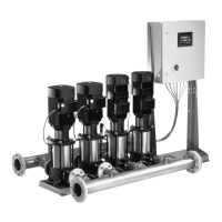
Grundfos BoosterpaQ systems are designed for transfer
and boosting of clean water in commercial buildings,
commercial landscape, industrial, and municipal applica-
tions. The BoosterpaQ range consists of three main groups:
S, F, and E. The main groups are divided into subgroups as
shown in the next column on this page.
Related Documents
For some BoosterpaQs, detailed information can be found
in the following related documents:
• Wiring Diagram
• Bill of Materials
• CR Pump Installation and Operating Instructions
• CRE Pump Installation and Operating Instructions
• Variable Frequency Drive Installation and Operating
Instructions
• BoosterpaQ Product Guide
SAFETY WARNING
Before beginning installation procedures,
these Installation and Operating Instruc-
tions should be studied carefully. Install-
ation and operation must be in accordance
with the National Electrical Code and local regula-
tions and accepted codes of good practice.
SHOCK HAZARD
A faulty motor or wiring can cause electrical shock
that could be fatal, whether touched directly or
conducted through standing water. For this reason,
proper grounding of the pump and system electri-
cal panel to the power supply’s grounding terminal
is required for safe installation and operation (see
“Electrical Connection,” page 6).
In all installations, the above-ground metal plumb-
ing should be connected to the power supply ground
as described in Article 250-80 of the National
Electrical Code.
 Loading...


