212 - Zone Name
For entry of a seven-character zone name (optional). Press
“Enter” to advance to the next letter position, then “+” or
“-” to select each character.
213 - Measuring Unit
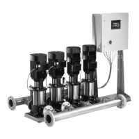
If the pressure sensor(s) features a measuring unit differ-
ent from the one set at the factory (default is psi), you
can change the measuring unit in Display 213. The need
for adjusting Display 213 normally occurs if the pressure
sensor(s) are changed to a different value. The pressure
sensor(s) may be changed, for example, due to a major
change in inlet pressure or a change in the application
requirements, such as increasing the pump stages to
account for a need for higher pressure.
IMPORTANT NOTE: When the measuring unit is changed, all
displays are automatically changed. However, the numeri-
cal values are not adjusted to reflect the change in units.
Example: If “bar” is changed to “psi,” all displays will reflect
“psi” automatically. But, a “bar” value of 1 ( for example)
set in a display will not automatically be changed to 14.5,
the conversion to psi. You must adjust all menu values to
reflect the new “psi” unit. Not doing so can cause symp-
toms which you may think are hardware related.
Example: You change “bar” to “psi.” You change “set-point
max.” from 6 bar to 87 psi, but you do not change the
“max. limit” value in Display 228, which was set to 10 bar.
You turn the BoosterpaQ on and it tries to ramp up to 87
psi, the set-point. But when it passes through 10 psi it stops
because the “max. limit” is still set to 10. It appears that
the BoosterpaQ has a hardware problem, but it only needs
to be set correctly. Be sure to check all values to reflect a
unit change. Check Displays 200, 201, 207, 218, 219, 220,
221, 228, 229, 231, 232, 233.
The following measuring units can be selected:
Pressure or pressure with pre-pressure measuring: bar,
mbar, psi, kPa
214 - Control Function
This display sets either direct or inverse reaction of the sys-
tem to deviations from the set-point.
[normal] If the actual value; for example pressure, is
lower than the set-point, the pump performance will be
increased.
[invers] If the actual value is higher than the set-point, the
pump performance is increased. This might be used in a
typical temperature application. For example, in a cooling
application when temperature goes above the set-point
(positive temperature direction), the system speeds up to
provide more cold water (positive speed direction).
The default is [normal].
216 - Pre-pressure Measuring
[on] Pre-pressure measuring is active
[off] Pre-pressure measuring is inactive
Pre-pressure measuring should be used if the system is run-
ning at a pre-pressure higher than 50% of the set-point and
10% of the pump max. pressure. Pre-pressure measuring,
combined with a pressure transducer on the suction inlet,
also provides low inlet pressure and dry run protection. Low
inlet pressure and dry run protection is also available using
a pressure switch or level control. However, these devices
do not provide the analog pressure information to the PFU
2000 which is used to smooth performance when the above
system characteristics are present. This setting must cor-
respond to the menu.
217 - External Set-point Influence
External influence on the set-point is effected via the PFU
2000 analog/digital Input 3, Terminal 15.
The most common use of this function is to have a remote
set-point adjustment (like from an energy management
system or building automation system).
Example: A building automation system is set up to control
the set-point of the system from a control room. The signal
from the control room will be 4-20mA.
First, turn the external influence (217) to “external” and
“%”:
Set A
influence _external %
Then pressing the down button, adjust the analog input sig-
nal (AI 3) to 4-20 mA and the percentages to 0% and 100%.
Set A extern 4-20 mA
3 0 % 100%
Press the down arrow again and set up the next two win-
dows according to the following:
Set A
0 % -> STOP psi
[off] External influence on the set-point via
the PFU 2000 is not possible
[extern] An external analog signal reduces the
set-point maximum.
Other influences are available for applications other than
pressure boosting. Please consult Grundfos if you want to
use one of the other influences.
219 - Discharge Pressure Sensor Measuring Range, Input 1
(AI 1)
In this display, the pressure sensor signal type is selected
and the minimum and maximum range of the sensor is
entered. The following signal types are available:
• 0-10 V
• 0-20 mA
• 4-20 mA (default, installed at the factory)
28
 Loading...


