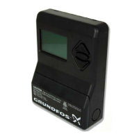
PMU 2000 LCD display notes
The following PMU 2000 LCD Display Notes must be used
in conjunction with the PMU 2000 Display Overview
Diagrams (“Overview” in this section) on pages 22 - 23. The
number at the beginning of each item is the display num-
ber shown on the Overview.
BASIC MENU
100 - Status Display
This is the first display which appears when the PMU 2000
is switched on. The display indicates:
• which pumps are connected to the PMU 2000,
• which pumps are running, switched off, or whether
any of the pumps are in an alarm state.
Pressing “Esc” repeatedly from any location in any menu
returns you to this display. If no button on the PMU 2000
is pressed within 15 minutes, it will automatically return to
this display.
The PMU 2000 LCD Overview Display examples indicate
the following (see pages 22 - 23):
• Pumps 1 and 2 are running [I]
• Pump 3 is not running [O]
• Pump 4 indicates a fault [A]. The fault is identified
under “Fault Indication Menu” (Display 600)
• Pump 5 is set to “Max” RPM
• Pumps 6 and 7 are allocated to a zone [-] but they have
not yet been connected to a PMU 2000, or the electric-
ity supply to the pump was never switched on
• Pump 8 has not been allocated to any zone [ ]
• A decimal point (.) between two pump numbers indi-
cate that these pumps have been connected to a PCU
2000. The display indicates that pumps 1,2,3, and 4
have been connected to a PCU 2000.
101 - Allocation to Zone
All pumps controlled by a PMU 2000 must be allocated to
Zone “A.” Numbers in the display not assigned to a pump
must be set to “-”. If “A” is not assigned to the pumps in the
system (for example, if it is a two pump system, one and
two should have an “A” below them), press “+” or “-” until
the “A” appears under each installed pump. Press “+” or “-”
to put a [-] under all other pump numbers. Press “Enter” to
store each entry and advance to the next pump number.
102 - Presetting
The factory setting for Display 102 is listed in this manual.
If a different presetting is shown, press “Enter” to jump to
Display 111, use the “UP” and “DOWN” arrows to find the
correct setting, press “Enter,” and then “Esc” to return to
Display 102. See Display 111.
103 - Day, Time, and Date (Day, Month, Year)
This is where the day of the week, time, and date are set.
Press “+” or “-” to set each character and press “Enter” to
store and advance to the next character. The format is dd-
mm-yy.
104 - Suppression of Alarm
The alarm output of the PMU 2000 will normally be active
when the red indicator light is on. If alarm suppression is
selected, the alarm output can be put out of operation for
15 minutes by pressing any key on the PMU 2000. If the
fault has not been remedied within 15 minutes, the alarm
will re-activate automatically.
[on] The alarm output will be suppressed for 15 min-
utes by pressing any of the keys on the PMU
2000
[off] The alarm output is active when the red indica-
tor light is on
Press “+” or “-” to set, and “Enter” to store
105 - Pump Communication
In certain cases, it may be expedient to stop some of the
pumps by switching off the electricity supply. This will nor-
mally cause a fault indication. If “off” is selected in “pump
comm. alarm,” the PMU 2000 will not indicate any com-
munication faults.
[on] The PMU 2000 will indicate a communication
fault
[off] The PMU 2000 will not indicate a communica-
tion fault
Press “+” or “-” to set, and “Enter” to store
106 - PMU Identification
The display indicates the software identification number of
the specific PMU 2000. Please have this number available
when contacting your distributor or Grundfos for service.
107 - PCU Identification
If a PCU 2000 is connected, this display indicates the soft-
ware identification number of the PCU 2000 to which the
pumps are connected. Please have this number available
when contacting your distributor or Grundfos for service.
108 - PFU Identification
This display indicates the software identification number
of the PFU 2000 (P/N on the PFU 2000 EPROM). Please have
this number available when contacting your distributor or
Grundfos for service. If this display does not come up, the
BUS connection is faulty.
End of Menu
You are at the bottom of this menu (same for all menus).
Press the “UP” arrow to move up through the menu, “Esc”
repeatedly to go to Display 101, or one of the function but-
tons to go to that function (for example: “Pump Status,”
“Zone Status,” etc.).
24

 Loading...
