Technical information (continued)
Minimum inlet pressure
Calculation of the inlet pressure “H” is recommended when...
• the liquid temperature is high
• the flow is significantly higher than the rated flow
• water is drawn from depths
• water is drawn through long pipes
• inlet conditions are poor.
To avoid cavitation, make sure that there is a minimum
pressure on the suction side of the pump. The maximum
suction lift “H” in feet can be calculated as follows:
H = p
b
x NPSHR — H
f
—
H
v
— H
s
p
b
= Barometric pressure in feet absolute.
(Barometric pressure can be set to 33.9 feet
at seal level.)
In closed systems, p
b
indicates the system
pressure in feet.
NPSHR = Net Positive Suction Head Required in feet.
(To be read from the NPSHR curve at the
highest flow the pump will be delivering.)
H
f
=
Friction loss in suction pipe in feet. (At the
highest flow the pumps will be delivering.)
H
v
=
Vapor pressure in feet.
(To be read from the vapor pressure scale.
H
v
depends on the liquid temperature
H
s
= Safety margin = minimum 2.0 feet
If the “H” calculated is positive, the pump can operate at a
suction lift of maximum “H” feet.
If the “H” calculated is negative, an inlet pressure of mini-
mum “H” feet is required.
Diaphragm tank
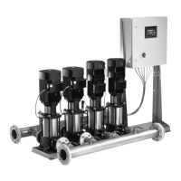
Please install ASME tank when required. To maintain UL/
cUL system approval, tanks attached to the BoosterpaQ
manifolds must be ASME certified.
Recommended minimum diaphragm tank sizes are as
follows:
Recommended Diaphragm Tank Size (gallons)
Pump Type ME MES MF MS
CR(E) 3 4.4 4.4 4.4 20
CR(E) 5 4.4 4.4 4.4 34
CR(E) 10 8.6 8.6 8.6 62
CR(E) 15 34 34 34 211
CR(E) 20 34 34 34 211
CR(E) 32 44 44 44 317
CR(E) 45 86 86 86 528
CR(E) 64 132 132 132 1056
CR90 - - 132 1056
If your system has minor leaks or experiences low inter-
mittent flows, a larger tank size may be required. These
are minimum sizes. Installing larger sizes can result in
smoother operation.
For MS systems the size of the diaphragm tank can also be
calculated by means of the following formula:
V =
Q x 15 x (14.5 + P
set
+ On/off
band
)
x
1
n
max
x On/off
band
x k k
V = Tank volume (gallons)
Q = Nominal flow for the smallest pump in
the system (gpm)
On/off
band
=
Difference between set-point and stop
pressure [psi]
p
set
=
Set-point [psi]
k = 0.9,
constant for diaphragm tank
pre-charge pressure
n
max
= Max. number of starts/stops per hour.
Operating conditions
Liquid Temp.: Maximum +176°F (+80°C) for standard
systems. Call for higher temperatures.
Ambient Temp.: 32°F to +104°F (0°C to +40°C)
Consult factory for higher tempera-
tures.
Operation above 131°F (55°C) is not
allowed.
Operating Press.: 150 psi or 230 psi, as rated for the
specific BoosterpaQ.
Do not exceed the pressure rating of
the tank.
Humidity: 95% maximum
Line impedance
It is recommended that the electricity supply have a line
impedance of 1% - 2% (3% max. for 3x575V supply).
Total Harmonic Distortion
The Total Harmonic Distortion on the voltage should be no
more than 5%.
Sound pressure level
For individual pump sound pressure values, call Grundfos.
The sound pressure level for a number of pumps can be
calculated as follows:
Lmax = Lpump + (n - 1) x 3
Lpump = Sound pressure level for one pump
Lmax. = Maximum sound pressure level
n = Number of pumps
36

 Loading...
