English (GB)
9
8.2.1 Liquid filling
1. Make sure that the discharge pipe is empty and
that the height from the centre of the suction port
to the first tapping point (H
1
) meets the
requirements. See section 6.2.2 Pipe connection
(self-priming pumps).
2. Open the isolating valves in the suction and
discharge pipes.
3. Open a tap close to the pump so that air can
escape.
4. Remove the filling plug in the pump. See fig. 11.
5. If a filling plug has been installed in the discharge
pipe, remove this plug and use this hole for filling.
Otherwise use the filling hole in the pump.
6. Fill the pump housing and the suction pipe
completely with liquid until a steady stream of
liquid runs out of the filling hole.
7. Fit and tighten the filling plug(s).
8. Start the pump and wait until liquid is pumped. If
you have used the filling hole in the pump, it may
be necessary to repeat steps 1 to 8 to ensure that
the pump is completely filled with liquid.
9. If the pump does not operate properly after
several start attempts, see section 12. Fault
finding.
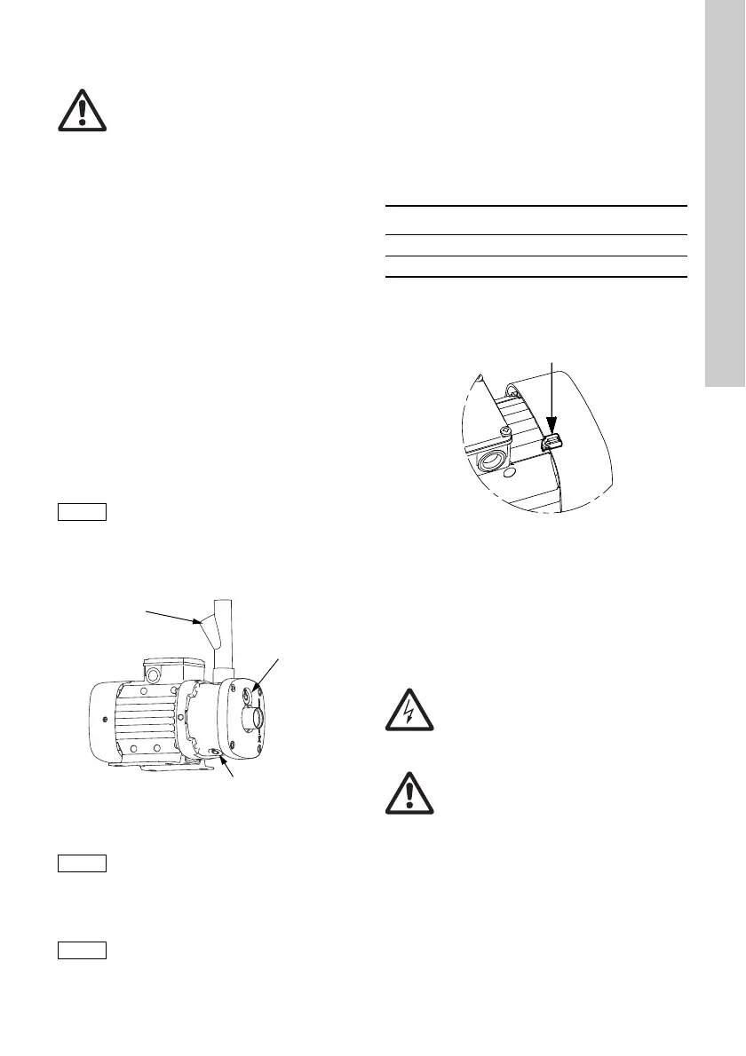
Fig. 11 Position of filling holes and drain hole
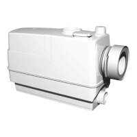
8.3 Checking the direction of rotation
The motor fan cover has an installation indicator.
See fig. 12. Based on the motor cooling air, it
indicates the direction of rotation of the motor.
Before the motor is started for the first time or if the
position of the indicator has been changed, the
indicator function should be checked, for instance by
moving the indicator field with a finger.
To determine whether the direction of rotation is
correct or wrong, compare the indication with the
table below.
* To reverse the direction of rotation, switch off the
power supply and interchange any two of the
incoming supply wires.
Fig. 12 Installation indicator
You can place the indicator in various positions on
the motor, but do not place it between the cooling
fins close to the screws that hold the fan cover.
The correct direction of rotation is also shown by
arrows on the motor fan cover.
9. Maintenance
The internal pump parts are maintenance-free. You
must keep the motor clean in order to ensure
adequate cooling of the motor. If the pump is
installed in dusty environments, clean and check the
pump regularly. Take the enclosure class of the
motor into account when cleaning.
The motor has maintenance-free, greased-for-life
bearings.
Warning
Pay attention to the direction of the vent
hole, and make sure that the escaping hot
or cold liquid does not cause injury to
persons or damage to the equipment.
If connected to a frequency converter, the
pump must run at maximum speed (3450
min
-1
) during startup.
TM05 8169 2013
The pump is allowed to run for 5 minutes
to attempt to suck liquid. If the pump does
not build up pressure and flow, repeat
steps 1 to 8.
The description below applies to
three-phase motors only.
Filling hole
Drain hole
Filling hole
Indicator field Direction of rotation
Black Correct
White/reflecting Wrong*
TM04 0360 1008
Warning
Before starting work on the pump, switch
off the power supply. Make sure that the
power supply cannot be accidentally
switched on.
Warning
Make sure that the escaping water does
not cause injury to persons or damage to
the equipment.