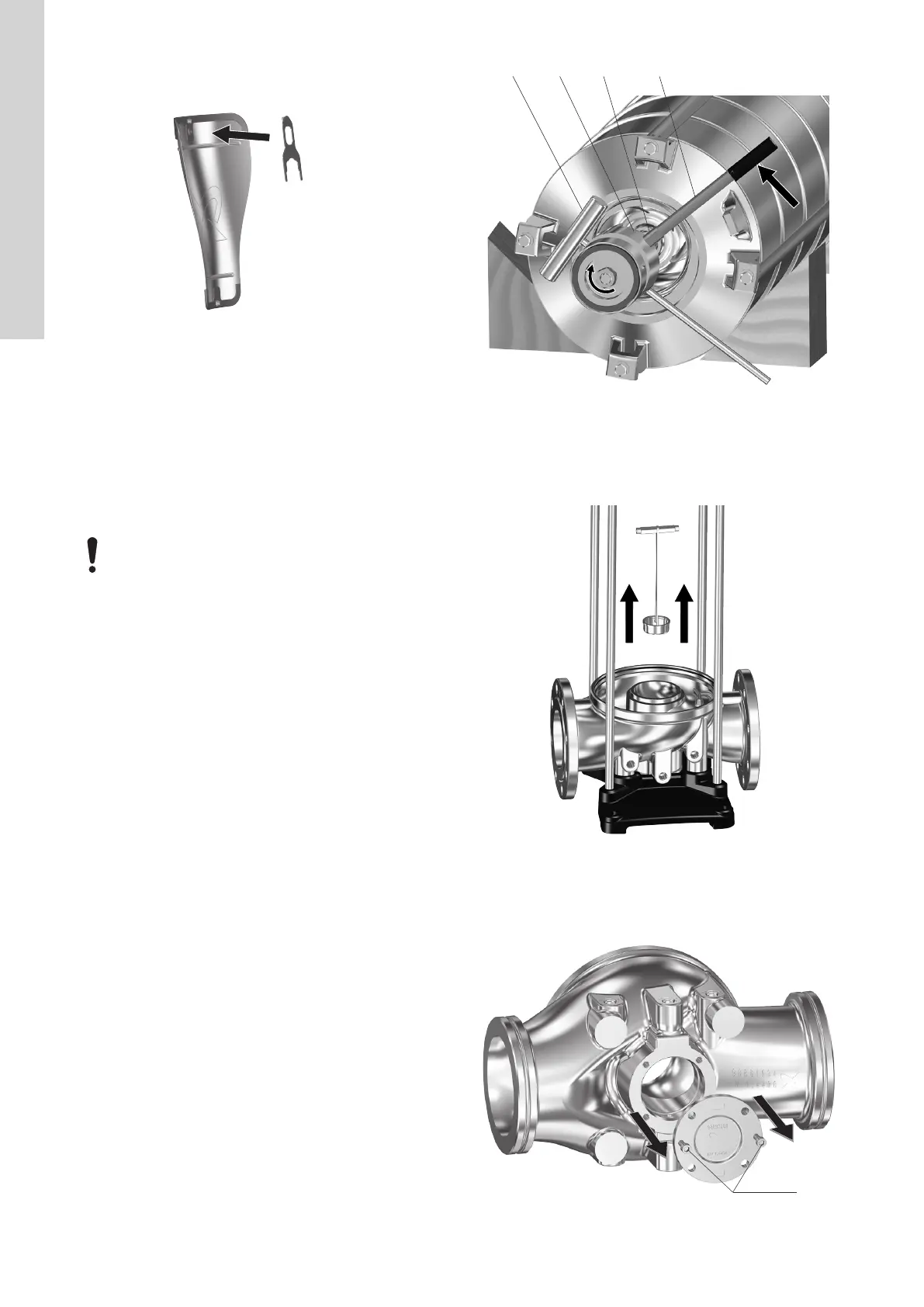
25. Pull the adjusting fork F free of the shaft (51) and place it on the
backside of one of the coupling guards (7). See the figure
below.
TM071743
Fitting adjusting fork Fon the backside of coupling guard (7)
26. Install the coupling guards (7) and tighten the screws (7a). See
the section on torques.
Related information
7.1 Torques
7.2 Lubricants
7.3.1 Special tools
3.3 Thrust-handling device
This section applies only for pumps fitted with a thrust-handling
device (120).
All parts for the thrust-handling device must be handled
very carefully in order to avoid damaging them.
There are two ways to service the thrust-handling device:
• by completely dismantling the entire pump.
See instructions in the section on servicing the thrust-handling
device by dismantling the entire pump.
• by positioning the pump horizontally and accessing the thrust-
handling device from the pump base.
See instructions in the section on servicing the thrust-handling
device from the pump base.
Related information
3.3.1 Servicing the thrust-handling device by dismantling the entire
pump
3.3.3 Servicing the thrust-handling device from the pump base
3.3.1
Servicing the thrust-handling device by dismantling the
entire pump
Preparations
Removing the thrust-handling device requires that the pump has
been dismantled as described in the sections on removal of the
motor and coupling and dismantling of the shaft seal, motor stool,
pump head cover, sleeve and chamber stack.
Dismantling
1. Lay down the chamber stack on a solid surface and take the
necessary precautions to prevent the chamber stack from
moving while working on it.
2. Loosen and remove the nut (120f) and washer (120e). Note that
the nut features a left-handed thread. Use service tools C, D, O
and P to hold the shaft when loosening the nut (120f).
TM071746
Dismantling thrust-handling device from pump shaft
3. Remove thrust-handling-device wear parts (120a,120b, 120c,
120d). The parts come out together.
4. Remove the stationary ring (120g) together with the lifting plate
(120h) by using service tool G for pulling out the parts.
TM071745
Removing stationary ring (120g) and lifting plate (120h)
5. Remove the bolts (26b) from the pump base (6).
6. Remove the flange (120k) by using two bolts (26b) as
extractors.
TM071747
Extracting the flange
10
English (GB)

 Loading...


