English (GB)
8
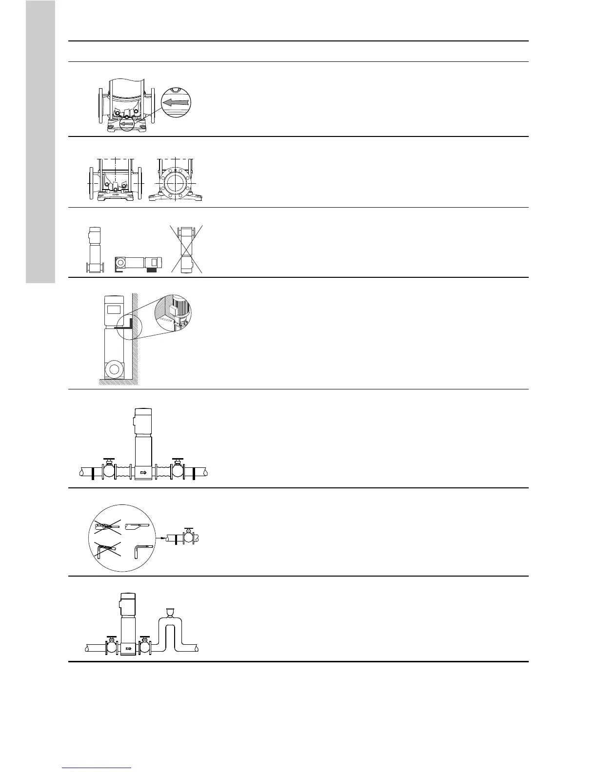
Illustration Information
1
TM06 9134 1617
Arrows on the pump base plate show the direction of flow of liquid
through the pump.
2
TM06 9156 1717
These dimensions are stated on page 26:
• port-to-port lengths
• dimensions of the base plate
• pipe connections
• diameter and position of anchor bolts.
3
TM07 0783 0218
The pump can be installed vertically and horizontally. If you wish to
install a pump horizontally, it must be ordered with support brackets
fitted from factory and a foot-mounted motor.
3a
TM05 7705 1013
Additional support. As the centre of gravity of the pump is relatively
high, we recommend that pumps installed on ships, in areas with risk
of earth quake or in systems which can be moved, are equipped with
an additional support bracket. You can fit the bracket from the motor
stool to the bulkhead of the ship, a rigid wall in a building or to a rigid
part.
4
TM02 0116 3800
To minimise possible noise from the pump, we recommend that you fit
expansion joints on either side of the pump.
Build a foundation and carry out mechanical installation as described
in section 3.1.3 Foundation.
Fit isolating valves on either side of the pump to avoid draining the
system if the pump needs to be removed for cleaning, repair or
replacement.
Always protect the pump against backflow by means of a non-return
valve.
5
TM02 0114 3800
Install the pipes so that air pockets do not occur.
6
TM02 0115 3800
Fit a vacuum valve close to the pump if the installation has one of
these characteristics:
• The outlet pipe slopes downwards away from the pump.
• There is a risk of siphon effect.
• Protection against backflow of unclean liquids is needed.

 Loading...


