4
50 Hz 60 Hz
Stages Stages
CR, CRI, CRN 1s 2 to 36 2 to 25 145 / 10
27 217 / 15
CR, CRI, CRN 1 2 to 36 2 to 25 145 / 10
27 217 / 15
CR, CRI, CRN 3 2 to 29 2 to 15 145 / 10
31 to 36 17 to 25 217 / 15
CR, CRI, CRN 5 3 to 16 2 to 9 145 / 10
18 to 36 10 to 24 217 / 15
CR, CRI, CRN 10 1 to 6 1 to 5 116 / 8
7 to 22 6 to 18 145 / 10
CR, CRI, CRN 15 1 to 3 1 to 2 116 / 8
4 to 17 3 to 12 145 / 10
CR, CRI, CRN 20 1 to 3 1 116 / 8
4 to 17 2 to 10 145 / 10
CR, CRN 32 1-1 to 4 1-1 to 2 58 / 4
5-2 to 10 3-2 to 6 145 / 10
11 to 14 7-2 to 11-2 217 / 15
CR, CRN 45 1-1 to 2 1-1 to 1 58 / 4
3-2 to 5 2-2 to 3 145 / 10
6-2 to 13-2 4-2 to 8-1 217 / 15
CR, CRN 64 1-1 to 2-2 1-1 58 / 4
2-1 to 4-2 1 to 2-1 145 / 10
4-1 to 8-1 2 to 5-2 217 / 15
CR, CRN 90 1-1 to 1 58 / 4
2-2 to 3-2 1-1 to 1 145 / 10
3 to 6 2-2 to 4-1 217 / 15
CRT 2 2 to 11 2 to 6 145 / 10
13 to 26 7 to 18 217 / 15
CRT 4 1 to 12 1 to 7 145 / 10
14 to 22 8 to 16 217 / 15
CRT 8 1 to 20 1 to 16 145 / 10
CRT 16 2 to 16 2 to 10 145 / 10
CR, CRX, CRN 8 1 to 6 1 to 4 87 / 6
7 to 20 5 to 16 145 / 10
CR, CRX, CRN 16 2 to 3 2 to 3 87 / 6
4 to 16 4 to 10 145 / 10
CRN-SF all all 72 / 5*
362 / 25**
* while pump is off or during start-up
** during operation
50 Hz 60 Hz
Stages Stages
CR, CRI, CRN 1s
Oval flange 1 to 23 1 to 17 232 / 16
FGJ, PJE 1 to 36 1 to 27 362 / 25
CR, CRI, CRN 1
Oval flange 1 to 23 1 to 17 232 / 16
FGJ, PJE 1 to 36 1 to 27 362 / 25
CR, CRI, CRN 3
Oval flange 1 to 23 1 to 17 232 / 16
FGJ, PJE 1 to 36 1 to 27 362 / 25
CR, CRI, CRN 5
Oval flange 1 to 22 1 to 16 232 / 16
FGJ, PJE 1 to 36 1 to 24 362 / 25
CR, CRI, CRN 10
Oval flange 1 to 10 145 / 10
Oval flange 1 to 16 232 / 16
FGJ, GJ, PJE 1 to 16 1 to 10 232 / 16
FGJ, GJ, PJE 17 to 22 12 to 17 362 / 25
CR, CRI, CRN 15
Oval flange 1 to 7 1 to 5 145 / 10
FGJ, GJ, PJE 1 to 10 1 to 8 232 / 16
FGJ, GJ, PJE 12 to 17 9 to 12 362 / 25
CR, CRI, CRN 20
Oval flange 1 to 7 1 to 5 145 / 10
FGJ, GJ, PJE 1 to 10 1 to 7 232 / 16
FGJ, GJ, PJE 12 to 17 8 to 10 362 / 25
CR, CRN 32 1-1 to 7 1-1 to 5 232 / 16
8-2 to 12 6-2 to 8 362 / 25
13-2 to 14 9-2 to 11-2 580 / 40
CR, CRN 45 1-1 to 5 1-1 to 4-2 232 / 16
6-2 to 9 4-1 to 6 362 / 25
10-2 to 13-2 7-2 to 8-1 580 / 40
CR, CRN 64 1-1 to 5 1-1 to 3 232 / 16
6-2 to 8-1 4-2 to 5-2 362 / 25
CR, CRN 90 1-1 to 4 1-1 to 3 232 / 16
5-2 to 6 4-2 to 4-1 362 / 25
CRT 2 2 to 26 2 to 18 305 / 21
CRT 4 1 to 22 1 to 16 305 / 21
CR, CRX, CRN, CRT 8 1 to 12 1 to 8 232 / 16
14 to 20 10 to 16 362 / 25
CR, CRX, CRN, CRT 16 1 to 8 1 to 8 232 / 16
10 to 16 10 to 12 362 / 25
Minimum Inlet Pressures
All CR, CRI, CRX, CRN NPSHR + 2 feet
CRN-SF 29 psi (2 bar)
Maximum Inlet Pressures
Maximum Operating Pressures
at 250° F (194° F for CRN-SF)
Consult Grundfos for other working conditions.
Select pump location
The pump should be located in a dry, well-ventilated area which is not subject to freezing or extreme variation in temperature. Care must be taken
to ensure the pump is mounted at least 6 inches (150 mm) clear of any obstruction or hot surfaces. The motor requires an adequate air supply to
prevent overheating and adequate vertical space to remove the motor for repair. For open systems requiring suction lift the pump should be
located as close to the water source as possible to reduce piping losses.
Foundation
Concrete or similar foundation material should be used to provide a secure, stable
mounting base for the pump. Bolt hole center line dimensions for the various pump
types are given in Figure 1. Secure the pump to the foundation using all four bolts and
shim pump base to assure the pump is vertical and all four pads on the base are proper-
ly supported. Uneven surfaces can result in pump base breakage when mounting bolts
are tightened.
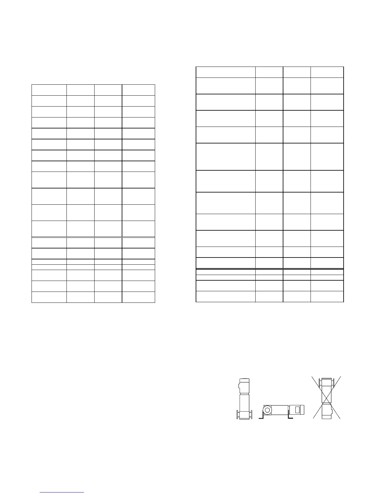
The pump can be installed vertically or horizontally (see drawing at right). Ensure that an
adequate supply of cool air reaches the motor cooling fan. The motor must never fall
below the horizontal plane.
Arrows on the pump base show the direction of flow of liquid through the pump.
To minimize possible noise from the pump, it is advisable to fit expansion joints on either side of the pump and anti-vibration mountings between
the foundation and the pump.
Isolating valves should be fitted either side of the pump to avoid draining the system if the pump needs to be cleaned, repaired or replaced.
Pre-installation Checklist (continued)
LCPTL003_CR I&O_Rev0104.qxd 1/26/2004 11:58 AM Page 4
 Loading...


