EasyManuals Logo

Grundfos CRN Series Service Instructions

Grundfos CRN Series
32 pages
To Next Page IconTo Next Page
To Previous Page IconTo Previous Page
Page #20 background imageLoading...
Page #20 background image
English (GB)
20
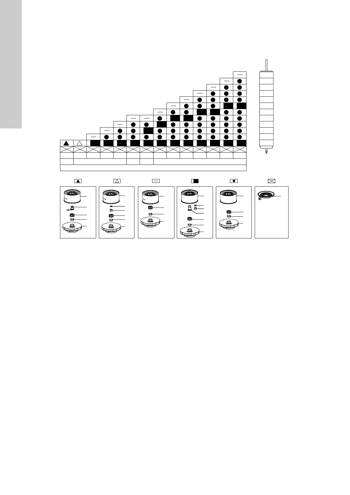
7.4 Order of assembly for chambers and impellers
The assembly of the pump is illustrated in the following drawings.
Each symbol corresponds to a different chamber.
Note: Pos. 49 is the standard size impeller. Pos. 49a is an
impeller with reduced diameter, 2/3 of standard size.
TM06 8473 0917
3
4
5
6
2
1
7
8
9
10
11
12
4
44
4a
47a
3
3a
47a
48
49b
49
49a
49
49a
49
49a
49
49a
49
49a
3a
48
49b
48
48a
49b
48
48a
48
49b
49b
47a
47g
47g
47a
Stage
2 3 4 5 6 7 8 9 10 11 1211
CR95
5
60 Hz50 Hz

Other manuals for Grundfos CRN Series

Questions and Answers:

Question and Answer IconNeed help?

Do you have a question about the Grundfos CRN Series and is the answer not in the manual?

Grundfos CRN Series Specifications

General IconGeneral
Pump TypeCentrifugal, multistage
MaterialStainless steel (AISI 304 or 316)
ApplicationsWater supply, pressure boosting, industrial processes
Impeller MaterialStainless steel (AISI 304 or 316)
ConnectionsFlanged or threaded
Speed2900 rpm
Temperature Range-10°C to +120°C
Inlet/Outlet SizeDN 25 to DN 100

Related product manuals