2. Product introduction
2.1 Product description
Grundfos E-pumps are mounted with frequency-
controlled permanent-magnet MGE motors for single-
phase or three-phase power supply connection. The
motors incorporate a PI controller.
You can connect the motors to a signal from an
external sensor and a setpoint signal enabling control
in closed loop. You can also use the motors for an
open-loop system in which the setpoint signal is used
as a speed control signal.
The motors incorporate an operating panel which is
available in various versions.
Detailed motor settings are made with Grundfos GO.
Furthermore, you can read important operating
parameters via Grundfos GO.
The motors incorporate a functional module. The
functional module is available in various versions with
different inputs and outputs.
You can fit the motors with a Grundfos add-on
communication interface module (CIM). The module
enables data transmission between the motor and an
external system, for example a BMS or SCADA
system. The module communicates via fieldbus
protocols.
You can connect several motors together via radio or
bus communication to create a multimotor system.
2.1.1 Pumps without a factory-fitted sensor
The pumps have a built-in PI controller and can be
set for an external sensor enabling the control of the
following parameters:
• constant pressure
• constant differential pressure
• constant temperature
• constant differential temperature
• constant flow rate
• constant level
• constant curve
• constant other value.
The pumps have been factory-set to constant-curve
control mode. You can change the control mode with
Grundfos GO, HMI 300, HMI 301 or Grundfos GO
Link.
2.1.2
Pumps with a factory-fitted pressure sensor
The pumps have a built-in PI controller and are set for
a pressure sensor enabling the control of the outlet
pressure.
The pumps have been factory-set to constant-
pressure control mode. The pumps are typically used
to keep a constant pressure in variable-demand
systems.
2.2
Intended use of the product
Only use the CR, CRN pumps according to the
specifications stated in the installation and operating
instructions.
Related information
1.1 Related instructions
2.3 Identification
2.3.1 Identification of the pump model
Identify the pump by the nameplate on the pump. See
description of the nameplate and type key in the
related installation and operating instructions.
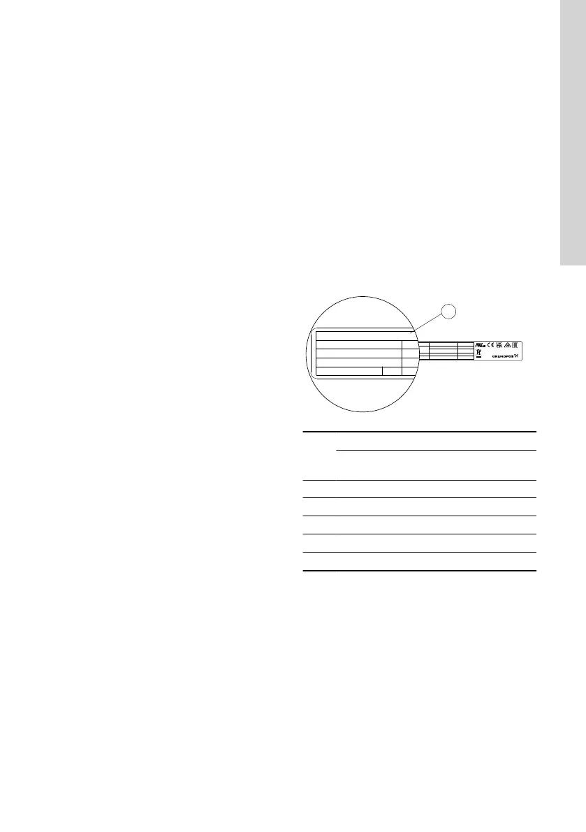
2.3.2 Identification of the motor model
Identify the motor by means of the nameplate on the
terminal box.
Model J
PB
FM
HMI
CIM
Made in Hungary
VARIANT
Hp
rpm
:
:
:
:
Xxxxxxxxxxx
E.P. Motor
DK - 8850 Bjerringbro, Denmark
Se
Type
:
P.N.
:
MGE132BA 2-FF300-JA
JA
TM083951
Motor
[kW]
3 × 380-500 V 3 × 200-240 V
1450-2200
rpm
2900-4000/
4000-5900
rpm
3400-4000
rpm
2.2 • - •
3 • • •
4 • • •
5.5 • • •
7.5 • • -
11 - • -
Model K
Env.
PF:
Tam
DE:
NDE:
Wgt: kg
Type:Type:
MGE160A 2-FF300-KA
P.N.: -V
OUTPUT Variant
V
Hz
A
P2:
PB:
FM:
HMI:
CIM:
kW
rpm
%
n:
PDS Eff
xxxv
:
98100448
IE5
IES2
Made in Hungary
DK-8850 Bjerringbro Denmark
K
A
TM083907
7
English (GB)
 Loading...