7
2. Product description
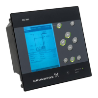
The CU 361 is a control unit designed for Dedicated
Controls systems. The CU 361 is used for the control
and monitoring of one or two pumps in a wastewater
pit.
Fig. 1 CU 361
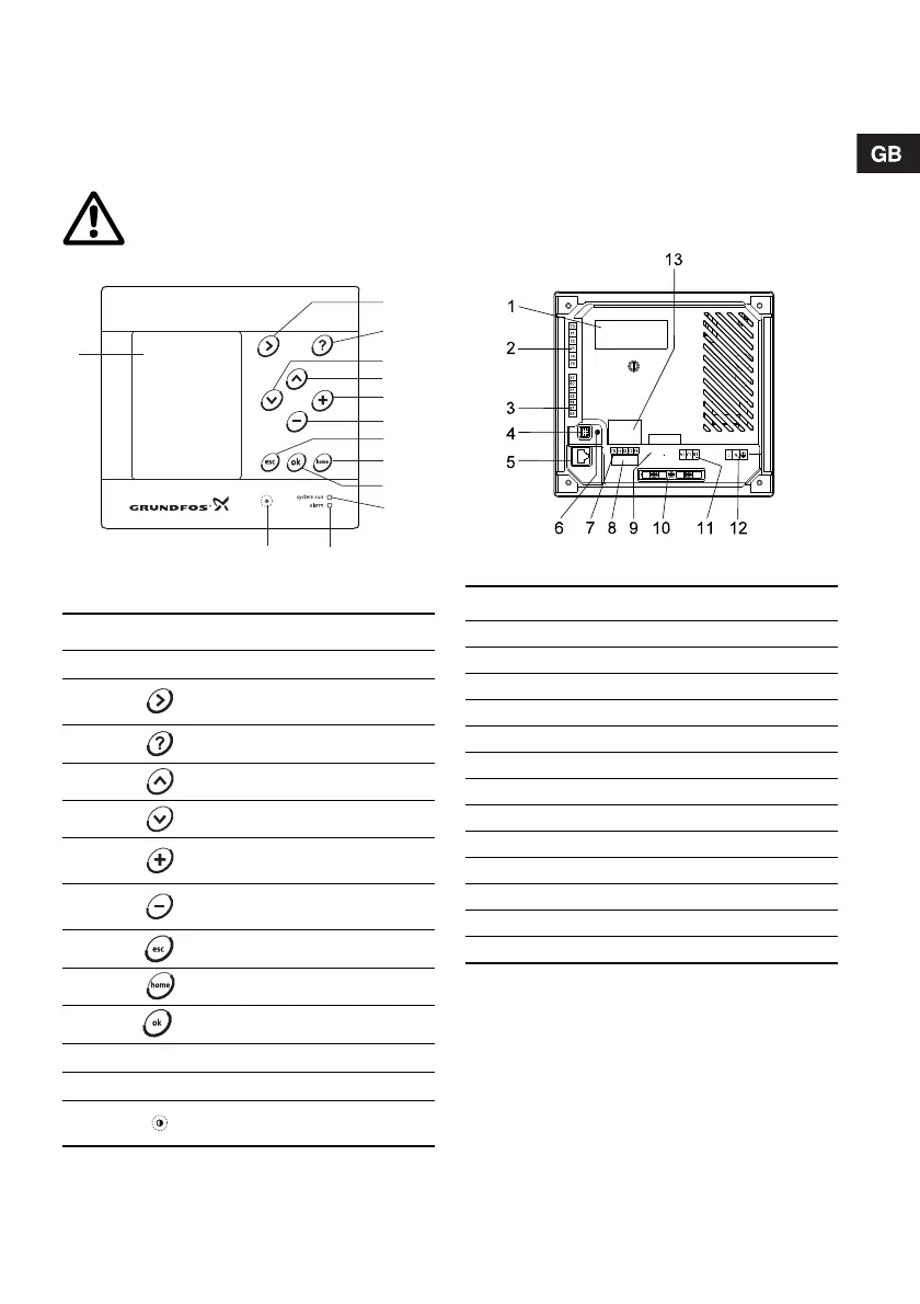
2.1 Indicator lights
The CU 361 has one green and one red indicator
light.
The green indicator light is on when the power
supply has been switched on.
The red indicator light is on when the system is in a
state of warning or has been stopped due to a fault.
2.2 Terminals
Fig. 2 Back of CU 361
Warning
If the CU 361 is used in a manner not
specified by the manufacturer, the
protection provided by the CU 361 may
be impaired.
TM04 2394 2508
Pos. Description
1LCD display
2
Changes to next column in menu
structure
3 Changes to help text
4 Goes up in lists
5 Goes down in lists
6
Increases the value of a selected
parameter
7
Reduces the value of a selected
parameter
8 Goes one display back
9 Goes back to the Status menu
10 Saves a value
11 Green indicator light (operation)
12 Red indicator light (alarm)
13
Changes the contrast of
the display
TM04 2064 2508
Pos. Description
1 Nameplate
2 Terminals for digital output relays
3 Terminals for analog inputs
4 Service connection
5 Ethernet (RJ45)
6 Voltage indicator
7 Terminals for digital inputs
8 Terminals for backup battery
9 Terminals for CIM module (optional)
10 Cable clamps for GENIbus connections
11 Internal GENIbus connection
12 Terminal for power supply
13 Label for backup battery