9
4.1 Location
The CU 361 is designed for installation in the front of
a control panel or a separate cabinet.
For outdoor installation the CU 361 must be mounted
in a control cabinet with an enclosure class of
minimum IPX4.
4.2 Enclosure class
The CU 361 is IP54 when mounted in the front of an
IPX4 enclosure. The cabinet must be of a flame-
retardant material.
For USA and Canada
The CU 361 is type 3R when mounted in the front of
a cabinet with type rating 1, 2, 3, 3R, 5, 12, 12K or
13.
4.3 Terminals
All terminals are suitable for conductors of 0.5 to
2.5 mm
2
or AWG 20-13.
4.4 Cables
Cables must be rated min. 70 °C.
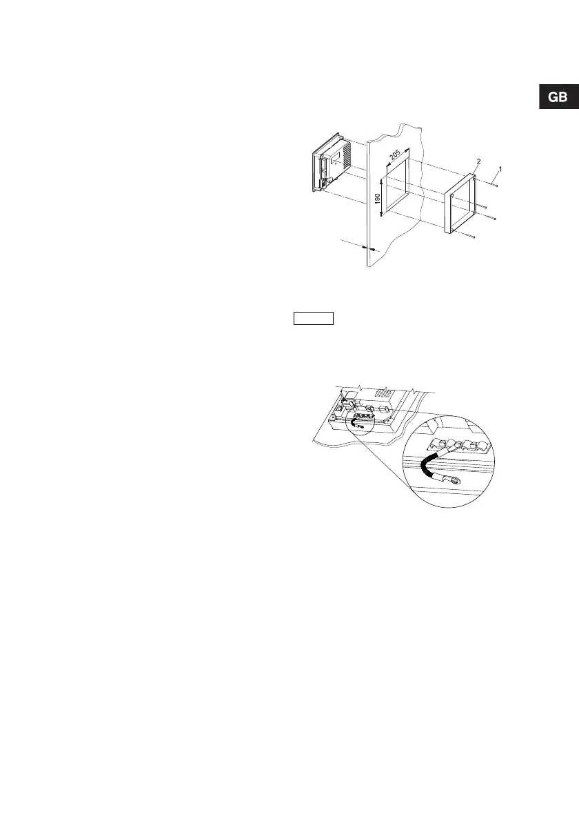
5. Mechanical installation
Fasten the CU 361 with the four screws, M5 x 10,
supplied with the unit (pos. 1).
Maximum torque: 1.4 Nm.
Dimensions of the CU 361, see section
14. Dimensions.
Fig. 6 Mounting in panel front (standard)
Connect the earth terminal (between the cable
clamps) on the CU 361 to the mounting frame
(pos. 2, fig. 6). See fig. 7.
Fig. 7 Earth connection
TM03 1301 4105
In order to achieve enclosure class
IP54, the CU 361 must be mounted
in a panel or cabinet.
TM04 2066 1908