8.1.4 Float switch functions
This menu allows the user to select the functions of the connected float switches.
Each float switch is linked to a function. "Saved" and "New" configurations can be seen in this display.
The individual configurations are defined by Grundfos and optimised relative to the number of pumps and number of float switches. The
individual configuration is shown in a table below the display.
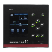
The individual displays show how the connected float switches are intended to affect the system.
Saved functions are shown on the left of the display.
1. Select a configuration to see other options.
2. Tick the box to the right of the configuration by pressing [OK].
3. Select "Overflow switch", if needed.
4. Select switch type for the input (NO/NC).
If used, the overflow switch must be connected to terminal DI3 of CU 362.
Path: Settings > Basic functions > Float switch function
Related information
6.2 Start and stop levels
8.1.4.7 Analog sensor with safety float switches
8.2.16 Overflow calculation
8.1.4.1
Drain function, one pump and two float switches
TM077561
Display: drain function, one pump and two float switches
TM028114
Drain function, one pump and two float switches
Float switch
Configuration
1 2 3
2 Start High level Start/stop
1 Stop Start/stop Dry running
26
English (GB)
 Loading...
