Do you have a question about the Grundfos AR and is the answer not in the manual?
Explains the manual's purpose and relation to pump manuals.
Information on obtaining further service details.
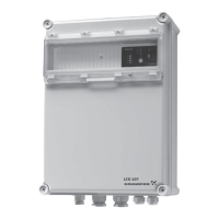
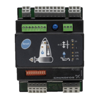
Describes available mounting options for the AR control unit.
Details about cables and plugs for the AR control unit.
Specifies the enclosure class ratings and conditions.
Lists standards and tests related to EMC protection.
Details on power supply voltage and mains impedance.
Specifies permissible environmental conditions for operation.
Provides diagrams with dimensions for mounting configurations.
States the weight of the AR control unit.
Lists the materials used for the AR control unit enclosure.
Discusses sensor requirements like Hall sensor for stroke control.
General guidance and warnings for installation procedures.
Specifies requirements for the installation site.
Instructions for safely switching the AR control unit on and off.
Details on mounting the control unit on a pump's terminal box.
Instructions for wall mounting the AR control unit.
Lists functions, modes, inputs, and outputs for electronic control.
Provides wiring diagrams for various control unit functions.
Wiring details for diaphragm leakage and dosing controller connections.
Wiring for current output and remote on/off inputs.
Wiring for stroke, pre-empty, and error signals.
Wiring for remote on/off, contact, and current inputs.
Wiring for empty and pre-empty signal inputs.
Lists available accessories like cables and plugs with product numbers.
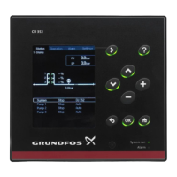
Identifies and explains the control buttons and display indicators.
Describes the display test performed upon pump startup.
Outlines the different menu levels for settings and operations.
How to use continuous operation for deaeration and suction.
How to lock the pump to prevent manual stopping.
Functionality of pre-empty and empty tank signals.
Explains the diaphragm leakage detection function and display.
Describes Hall sensor function for motor monitoring.
How to control the pump remotely.
Functionality and connection of the dosing controller.
Explains available signal outputs for external communication.
Outputting pump stroke frequency as a current signal.
How the error signal is used to report states to the control room.
Signal output for pump strokes or pre-empty conditions.
Guide to selecting and setting pump operating modes.
How to operate the pump in manual mode with adjustable flow.
Using contact signals to control dosing strokes with a multiplier.
Using contact signals to control dosing strokes with a divisor.
Controlling pump via external current signal.
Steps to enter and leave the second function level.
How to set or change the access code for security.
How to switch the dosing controller on/off.
How to store excess contact inputs for later processing.
How to control dosing capacity via current signal.
How to view the total operating time of the drive.
How to change the electronics' switch assignments.
Configures relay function for stroke or pre-empty signals.
Configures remote off input as normally open or closed.
Configures pre-empty signal input as normally open or closed.
Configures empty signal input as normally open or closed.
Configures error signal output as normally open or closed.
Configures relay output for stroke/pre-empty signals.
Enables or disables the Hall sensor function.
Enables or disables the pump run locking function.
Configuration for the master pump in a master/slave setup.
Configuration for slave pumps in a master/slave setup.
| Housing material | Plastic |
|---|---|
| Input Signals | Analog, digital |
| Output Signals | Analog, digital |
| Communication | Modbus |
| Operating temperature | -10°C to +55°C |
| Storage temperature | -20°C to +60°C |
| Relative humidity | 5% to 95% (non-condensing) |
