English (GB)
9
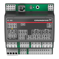
7.2 Connection diagram for the AR control unit
Fig. 7 Connection diagram
7.2.1 Diaphragm leakage detection / dosing controller
Socket 1
For diaphragm leakage detection (MBS) and/or dosing controller
(DC).
The diaphragm leakage detection and dosing controller are
pre-assembled with an M12 plug for socket 1.
If the diaphragm leakage sensor and the dosing controller are to
be used at the same time, both cables must be assembled in one
plug.
• Connect the cables according to the following table.
* MBS is an abbreviation of the function in German language "Membranleckagesignalisierung" = diaphragm leakage detection
7.2.2 Current output / remote on/off
Socket 2
For the remote on/off input and current output.
TM03 6355 4506
Warning
For the connection of one cable, use a plug adapter
with simple cable entry, for the connection of two
cables, use a plug adapter with double cable entry,
otherwise the protection will be lost!
2
1
2
3
4
4
1
2
3
4
5
1
2
3
3
1
2
3
4
1
1
2
3
4
5
Socket 1
Used for / wire colour
Diaphragm leakage detection (MBS)*
Dosing controller
Pin Assignment Cable 0.8 m
Cable 3 m
(without plug)
1+12 V Brown
2 MBS/GND White White
3 MBS supply Blue Yellow
4 Dosing controller output Blue
5 MBS output Green/yellow Green
The current output is not designed for controlling
secondary pumps in master/slave operation.
Socket 2 Cable Used for
Pin Assignment Wire colour +/- current output Remote on/off
1+5 V Brown +
2 Remote on/off input White x
3GND Blue x
4 Current output Black -