Do you have a question about the Grundfos IO 242 and is the answer not in the manual?
The Grundfos IO 242 is a pump module designed to work in conjunction with other Grundfos controllers and modules, specifically the Grundfos CU 24X control unit. This module is engineered to manage and monitor the operational conditions of one or two pumps, providing essential input and output signals for comprehensive pump system control.
The primary function of the IO 242 pump module is to facilitate the control and monitoring of pump systems. When integrated with a Grundfos CU 24X control unit, it enables the control unit to manage one or two pumps, overseeing their running conditions. The module serves as a central connection point for various sensors located in a pit or tank, as well as for the pump motors themselves. It processes analog and digital input signals for the CU 24X and provides digital outputs for external switch gear.
The IO 242 is designed for two main purposes: emptying a wastewater pit or filling a pit or tank. This versatility makes it suitable for a wide range of applications, including network pumping stations, main pumping stations, commercial buildings, and municipal systems. The control unit offers thermal protection (PTC) for connected motors, ensuring safe operation and preventing damage due to overheating. This PTC function meets performance level C, category 1, according to ISO 13849, highlighting its reliability in safety-critical applications.
The module incorporates a GENIbus interface, which is Grundfos's proprietary fieldbus for data transfer in motor and pump applications. GENIbus allows Grundfos devices to be networked and integrated into automation systems, with each device requiring a unique address. The GENIbus operates on the RS485 hardware standard, typically at a baud rate of 9600 bits/s, ensuring robust communication within the system.
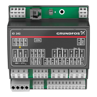
The IO 242 is designed for installation in a control panel, specifically for horizontal mounting on a 35 mm DIN rail (EN 50022). Its compact dimensions and recommended minimum clearance ensure it can be easily integrated into existing panel setups. Connecting the module to the DIN rail is a straightforward process, involving hooking the top onto the rail and pressing the bottom against it.
Electrical connections are made via spring clamps, simplifying wiring. Users must ensure the supply voltage matches the required 24 VDC and that polarity is correctly observed. The module is designed to ensure a good electrical contact to the DIN rail, which should also have a good connection to functional earth. Shielded cables are recommended for external GENIbus connections, with the shield connected to a cable clamp, to ensure EMC-correct installation and faultless operation in environments with other power equipment.
The GENIbus termination resistor DIP switch (SW1) allows users to configure the terminal impedance. This switch has two bits, SW1-1 and SW1-2, which can be set to "cut-in" or "cut-out" depending on whether the cable is terminated or unterminated, and the maximum cable length being used. This flexibility allows for optimal network performance based on the specific installation requirements.
The module's terminals are clearly labeled, providing connections for current transformers (optional), GENIbus, supply voltage, user-configurable output relays, digital inputs, analog or digital input, and PTC sensors. This comprehensive set of terminals allows for extensive customization and integration with various sensors and external switch gear. The user-configurable output relays (REL 3 and REL 4) offer normally open and normally closed options, providing flexibility in controlling external devices. Dedicated terminals for current transformers ensure accurate monitoring of pump motor currents.
The IO 242 pump module is not designed for field servicing; if it is found to be faulty, it must be replaced. However, regular inspections are recommended to ensure its full functionality. A comprehensive inspection should be performed every fifth year.
The recommended inspection procedure involves several steps:
When replacing the IO module, safety precautions are paramount. The power supply to the product and all other components with external supply must be switched off to prevent electric shock. Before disconnecting any wires, it is crucial to write down the terminal connections to ensure correct reconnection of the new module. After all wires are disconnected, the module can be gently pressed up and lifted off the DIN rail. The new module is then fitted, and all wires are reconnected according to the recorded connections.
The product is designed to be disposed of in an environmentally sound way at the end of its life cycle. Users are advised to use public or private waste collection services or contact the nearest Grundfos company or service workshop for guidance. The crossed-out wheelie bin symbol on the product indicates that it should not be disposed of with household waste but taken to a designated collection point for separate recycling, contributing to environmental protection and human health.
| Type | Control unit |
|---|---|
| Power supply | 24 V DC |
| Power consumption | 5 W |
| Ambient temperature | -20°C to +50°C |
| Protection class | IP20 |
| Housing material | Plastic |
| Relative humidity | 95% RH (non-condensing) |