TM075468
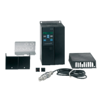
• Connect the shield to the earth terminal inside the control
cabinet.
• Do not twist shield ends, as this will destroy the shield effect at
high frequencies.
• Ensure that the DIN rail has a good connection to functional
earth.
The module has been designed to ensure a good electrical
contact to the DIN rail.
2.3 Electrical connection
2.3.1
Connecting the power supply
WARNING
Electric shock
Death or serious personal injury
‐ Switch off the power supply before making any
electrical connections.
‐ Make sure that the power supply cannot be switched
on accidentally.
Do not connect the phase inputs to the module if the input
is higher than 3 x 480 VAC.
Install the product by following the wiring practice rules of
IEC 60204-1 to avoid short circuit of the PTC sensor
wiring. This will secure the protective function of the PTC
sensor.
Changes or modifications not expressly approved by
Grundfos may void the user's authority to operate the
equipment.
1. Check that the supply voltage corresponds with the needed 24
VDC, and ensure that the polarity is connected correctly
according to the label on the product itself.
2. Connect the power cables and pump cables according to the
relevant electrical diagram.
3. Tighten the terminal screws to 0.5 Nm.
Remember to remove the jumper from the PTC terminal if you
are connecting cables from the temperature sensor to the PTC
terminal.
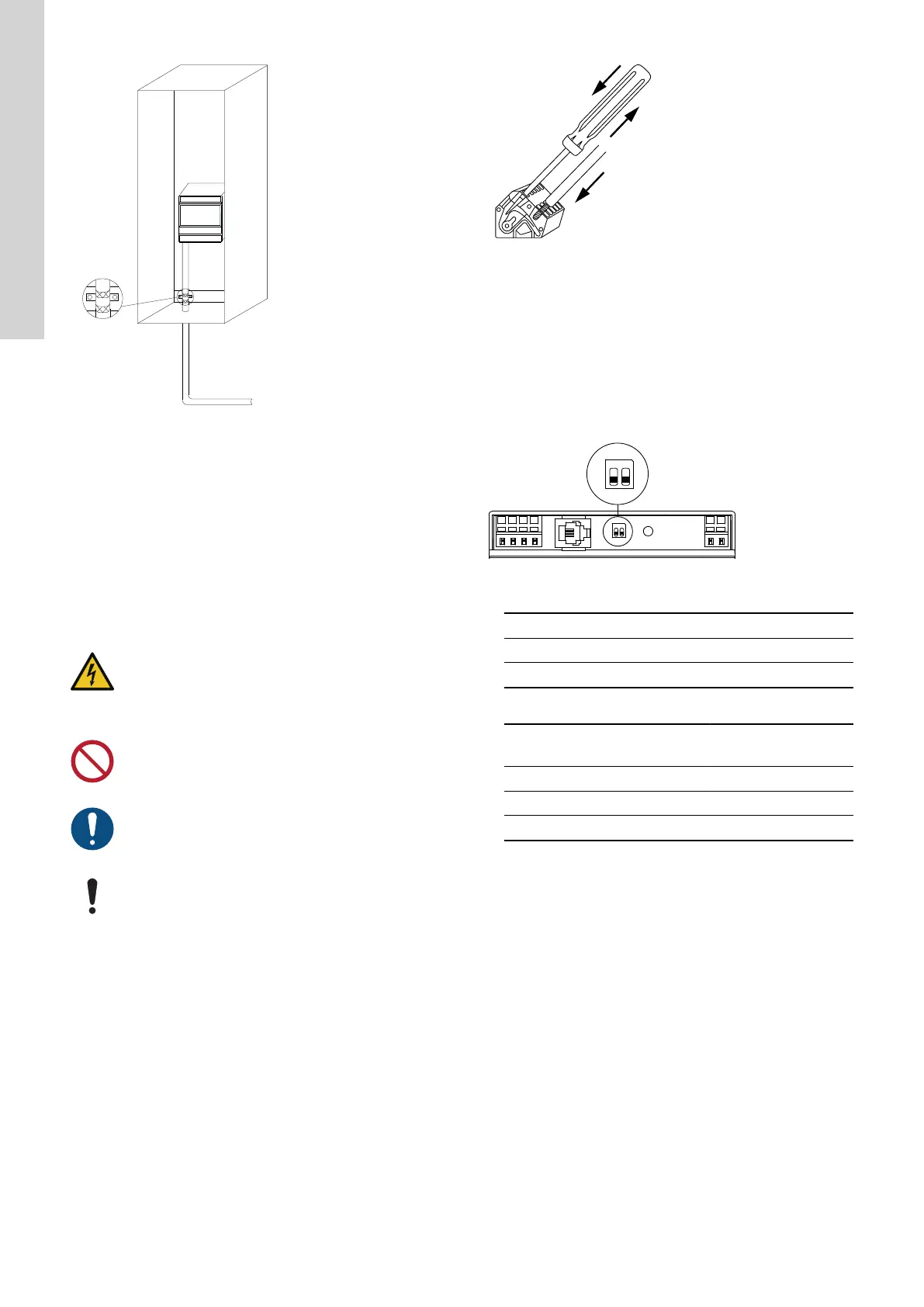
TM070570
Connecting a wire to a terminal with spring clamps
Related information
3.3 Terminals
3.6 PTC
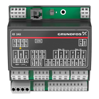
2.3.2 Setting the termination resistor
The GENIbus termination resistor DIP switch SW1 has two bits
switches, SW1-1 and SW1-2.
SW1-2 is used for cutting the terminal impedance in and out.
TM075594
1. Set the switches according to the table.
Status
SW1-1 SW1-2
Cut-in - ON
Cut-out - OFF
Maximum cable length
bit/s
Terminated cable
m [ft]
Unterminated cable
m [ft]
1200-9600 1200 [4000] 1200 [4000]
19200 1200 [4000] 500 [1700]
38400 1200 [4000] 250 [800]
3. Product introduction
3.1
Product description
The IO 242 pump module is used together with other Grundfos
controllers and modules. With a Grundfos CU 24X control unit, the
control unit will control one or two pumps, monitor the running
conditions of the pumps and have all the connections to sensors in
the pit or tank and pump motors. The pump module provides analog
and digital input signals for Grundfos CU 24X. It also provides
digital outputs used for external switch gear.
3.2
Intended use, IO 242
The control unit is designed to control one or two pumps. The
product can be configured for two purposes: emptying a wastewater
pit or filling a pit or tank. The product can be used for network
pumping stations, main pumping stations, commercial buildings and
municipal systems.
The product must not be exposed to aggressive solvents or oil-
containing liquids.
6
English (GB)
 Loading...